
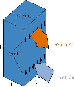
Fig. 1 – Ventilated cabinet
Introduction
Natural air convection is commonly applied as a cooling technique for electronic equipment of moderate power density such as telecommunication boxes. The main advantage of natural convection isits intrinsic reliability, because air movement is generated simply bydensity gradients, if an external body force field exists. However, due tothe relatively low efficiency of the cooling technique, the thermal designof the electronic equipment must be optimized, i.e. the geometricalconfiguration of the heat sources and the ventilated enclosure must beselected so as to generate an air flow rate which minimizes the averageand the maximum temperature rise inside the enclosure itself. Inparticular, the thermal behavior of a case depends on the balance betweenthe net buoyancy force and the friction losses along the whole air path.The latter takes into account the distributed pressure losses along thehot channels formed by electronic cards and the concentrated frictionlosses in the inlet-outlet vents [1-2].
In this paper a practical formula for the thermal design of theventilated enclosures is presented. The formula takes into accountimportant parameters such as power transferred to the cooling air, chimneyheight (distance between the inlet and outlet vents), volumetric air flowrate, vent area, and friction losses along all the air flow pattern.Application examples are given as illustrations of the practical formulaused as a preliminary tool for thermal design of natural ventilated boxes.
Experiments on a ventilated cabinet
The ventilated box usedduring the study is schematically shown in Fig. 1. Its dimensions are(WxLxH) 100 mm x 152 mm x 254 mm and it contains a series of equi-spaced,vertical heated cards (152 mm x 254 mm). The number of the boards placedin the enclosure is 6. It has been shown that this arrangement of thecards corresponds to an optimum board spacing of about 15 mm [3]. Theelectronic circuitry is simulated on each card by 12 rows of 12 electricresistors arranged in three equal sectors. The two vents (inlet andoutlet) are placed on the same wall of the box. Several experiments,performed with the same vent area for the previous tests, but with theoutlet vent on the opposite wall of inlet one, showed the same thermalbehavior.
The cooling air enters the case through the lower vent, removes afraction of the heat generated inside (in proportion to the total frictionlosses along the air path) and exits through the upper vent. The heat notremoved by the ventilation air draft is transferred to the externalambient by convection and radiation through the cabinet walls. To reducethe heat leakage through the walls and to simulate the presence of otheradjacent boxes, all the walls except the one with the vents were carefullyinsulated.
The air temperature distribution inside the box has been measured bymeans of 44 calibrated K-type thermocouples (±0.1 oC) arranged on each card at three different heights. The thermocouples are located near the thermal boundary layer on the heated side of the card and in the surrounding of the back side. The experiments have shown that the mean outlet air temperature is nearly identical to the integral averagevalue at the highest elevation of the box, while the inlet temperature isequal to the ambient temperature T0.
A simple correlation equation forthermo-circulation flow rate, useful for a preliminary thermal design ofcooled-air ventilated enclosures, can be obtained using the model sketchedin Fig. 2.
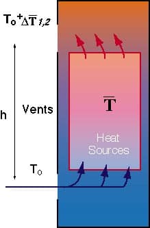
Fig. 2 – Thermal model
In a steady state condition the heat flux P’ (W) removed by the air is related to the inlet-outlet enthalpy variation![]() H1,2:
H1,2:
| Equation 1 |
and the buoyancy provides the fluid with kinetic energy:
| Equation 2 |
where ![]() is the volumetricair flow rate (m3/s),
is the volumetricair flow rate (m3/s),![]() 0and
0and ![]() are theexternal and internal air density (kg/m3)respectively, the latter evaluated at the mean inner air temperature
are theexternal and internal air density (kg/m3)respectively, the latter evaluated at the mean inner air temperature![]() (K), h is the chimney height, i.e. the distance between the center lines of the vents, Ke is the equivalent fluid resistance coefficient,u is the reference value for average air velocity (m/s), cp is the specific heat of air (J/kgK), and
(K), h is the chimney height, i.e. the distance between the center lines of the vents, Ke is the equivalent fluid resistance coefficient,u is the reference value for average air velocity (m/s), cp is the specific heat of air (J/kgK), and![]() T1,2 is the difference between the outlet-inlet airtemperatures (K). Assuming the air density inside the box as a linearfunction of the temperature and denoting by C=
T1,2 is the difference between the outlet-inlet airtemperatures (K). Assuming the air density inside the box as a linearfunction of the temperature and denoting by C= ![]() T 1.2 /
T 1.2 /![]()
![]() the ratiobetween the inlet-outlet air temperature difference and the mean inner airtemperature rise, and then combining the Eq.s (1) and (2), it is possibleobtain the simple formula:
the ratiobetween the inlet-outlet air temperature difference and the mean inner airtemperature rise, and then combining the Eq.s (1) and (2), it is possibleobtain the simple formula:
| Equation 3 |
| Ke =Kch+Kcon | Equation 4 |
| Kcon=Kin+Kout | Equation 5 |
| a) | the inner air temperature in the cabinet is equal to T |
| b) | the air flow rate through a single vent opening is equal to the total air flow rate V. divided by the number of single openings; |
| c) | since all the analysis parameters are considered average values, it has been assumed K= Kin=Kout . |
| Equation 6 |
| shape of outlets | circular holes, horizontal slots, vertical slots |
| inlet or outlet vent area | 600 10-6 m2;800 10-6 m2; 100010-6 m2 |
| hydraulic diameter | 3mm ; 4mm ; 5mm |
| porosity | 0.2 ; 0.33 |
| power removed by air | 5W ; 10W ; 15W |

Fig. 3 – Shape of the vents
A deeper analysis of the thermal behavior of the casing was reported in [4]. In the same paper, the relationships between K and ReDh, for the different shapes and porosities investigated, are shown. To make easier the utilization of Eq. (3), a relationshi relationship between K and ReDh, valid for all the three vent shapes and the two porosities investigated, is reported below:
| Equation 7 |
In this paragraph, the procedure for using the practical formula (Eq. (3)) is reported. The equation is not explicit, because in K the volumetric airflow rate
A flow chart (Fig. 4) that explains the steps of the iterative procedure is depicted above. Few iterations are necessary to reach the final valueof A. Several iterative results are listed in Table 1.
| Iteration number | Ain=Aout ·106m2 |
Number of holes |
| 1 | 400 | 20 |
| 2 | 613 | 31 |
| 3 | 629 | 32 |
| 4 | 637 | 32 |
| 5 | 644 | 32 |
| 6 | 643 | 32 |
P’ = 10 W, ![]() =50 oC, h=0.2 m, Dh=5 mm, T0=20oC,
=50 oC, h=0.2 m, Dh=5 mm, T0=20oC,

Fig. 4 – Flow chart of the iterative procedure (Eq. (3))
Application examples are given as illustrations of Eq. (3) as apreliminary tool for the thermal design of Fig. 5 (overleaf), the linesrepresent the predicted values of the inlet or outlet vent area A as afunction of the mean inner air temperature rise using Eq. (3) incomparison with some experimental data (Dh=5mm, three vent shapes, and three values by air). There is good agreementbetween the theoretical results and the experimental ones. In thisexample, it has been assumed Ain=Aout=A.
Conclusions
A practical formula for the thermal design ofventilated enclosures used in the electronic equipment is presented. Theformula takes into account several parameters, such as power removed byair, air flow resistance, average inner air temperature, inlet or outletvent area and chimney height. Obviously, this simple formula must be usedonly as a preliminary tool for the thermal design of casings containingelectronic boards. Deeper analysis can be performed using other techniquessuch as CFD (Computation Fluid Dynamics). Nevertheless, even though theflow pattern in a casing and along the electronic boards is very complex,the validity of the few simple formulas available in literature must bechecked by the users in order to know the error between the theoreticalanalysis and the real behavior of the enclosures. In other words, it isvery hard to make many tests to confirm the validation of the practicalformulas, because the parameters that can be involved in real applicationsare numerous. Simple formulas in many cases can be useful only for theevaluation of the vent area.

Fig. 5 – Inlet or outlet vent area A vs. mean inner airtermperature rises for three different values of power thermocirculationP’. Vents as circular holes, horizontal slots, and vertical slots (Dh=5mm)
References
| 1. | Ellison, G.N., Thermal Computations for Electronic Equipment, Van Nostrand Reinold Company, New York 1984, Re-print edition by Robert Z. Kreises Publishing Company, Malabar, Florida, 1989. |
| 2. | Guglielmini, G., Milano, G., and Misale, M., Some Factors Influencing the Optimum Free Air Cooling of Electronic Cabinets, in Heat Transfer in Electronic and Microelectronic Equipment, A.E. Bergles, Eds., Hemisphere Publications Corporations, pp. 311-325, New York, 1990. |
| 3. | Bar-Choen, A. and Rohsenow, W.M., Thermally Optimum Spacing of Natural Convection Cooled Parallell Plates, J. of Heat Transfer, Vol. 106, pp. 116-123, 1984. |
| 4. | Misale, M., Electronic Cabinet Cooling by Natural Convection: Influence of Vent Geometry, 3rd World Conference on Experimental Heat Transfer, Fluid Mechanics and Thermodynamics, Vol. 1, pp. 764-771, Honolulu, Hawaii, USA, 1993. |
| 5. | Braater, M.E., and Patankar, S.V., Analysis of Laminar Mixed Convection in Shrouded Arrays of Heated Rectangular Blocks, Int. J. Heat Transfer, Vol. 28, N. 9, pp. 1699-1709, 1985 |