As noted previously in this column, the trend of increasing electronic module power is making it more and more difficult to cool electronic packages with air. As a result there are an increasing number of applications that require the use of forced convection air-cooled heat sinks to control module temperature. An example of a widely used type of heat sink is the parallel plate configuration shown in Figure 1.
![]() |
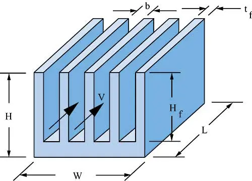
Figure 1. Parallel plate fin heat sink configuration.
In order to select the appropriate heat sink, the thermal designer must first determine the maximum allowable heat sink thermal resistance. To do this it is necessary to know the maximum allowable module case temperature, Tcase, the module power dissipation, Pmod, and the thermal resistance at the module-to-heat sink interface, Rint. The maximum allowable temperature at the heat sink attachment surface, Tbase, is given by
![]() |
The maximum allowable heat sink resistance, Rmax, is then given by
![]() |
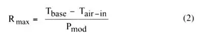
where Tair-in, is the temperature of the cooling air at the inlet to the heat sink passages. At this point many thermal engineers will start looking at heat sink vendor catalogs (or more likely today start searching vendors on the internet) to find a heat sink that will fit in the allowable space and provide a heat sink thermal resistance, Rhs, less than Rmax at some specified flow rate. In some cases, it may be useful to do a sizing to estimate Rhs for various plate-fin heat sink designs to determine if a feasible design configuration is possible. The remainder of this article will provide the basic equations to do this. The thermal resistance of the heat sink is given by
![]() |
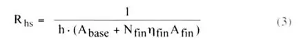
where h is the convective heat transfer coefficient, Abase is the exposed base surface area between fins, Nfin is the number of fins, fin is the fin efficiency, and Afin is the surface area per fin taking into account both sides of the fin.
To proceed further it is necessary to establish the maximum allowable heat sink volume in terms of width, W, height, H, and length in the flow direction, L. It is also necessary to specify a fin thickness, tfin. Using these parameters the gap, b, between the fins may be determined from
![]() |
The exposed base surface area may then be determined from
![]() |
and the heat transfer area per fin from
![]() |
At this point it is necessary to specify the air flow rate either in terms of the average velocity, V, between the fins or a volumetric flow rate, G. If a volumetric flow rate is used, the corresponding air velocity between the fins is
![]() |
To determine the heat transfer coefficient acting upon the fins, an equation developed by Teertstra et al. [1] relating Nusselt number, Nu, to Reynolds number, Re, and Pr number, Pr, may be employed. This equation is
![]() |
The Prandtl number is
![]() |
where is the dynamic viscosity of air, cp the specific heat of air at constant pressure, and k is the thermal conductivity of air. The Reynolds number used in (8) is a modified channel Reynolds number defined as
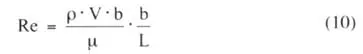
![]() |
where is the density of air. Equation (8) is based upon a composite model spanning the developing to fully developed laminar flow regimes and was validated by the authors [1] by comparing with numerical simulations over a broad range of the modified channel Reynolds number (0.26 <Reb < 175) and with some experimental data as well. Using the Nusselt number obtained in (8) the heat transfer coefficient is given by
![]() |
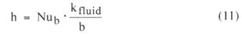
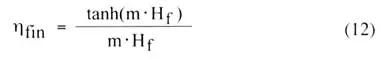
where kfluid is the thermal conductivity of the cooling fluid (i.e. air). The efficiency of the fins may be calculated using
![]() |
where m is given by
![]() |
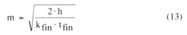
and kfin is the thermal conductivity of the fins.
Using these equations it is possible to estimate heat sink thermal performance in terms of the thermal resistance from the temperature at the base of the fins to the temperature of the air entering the fin passages. It may be noted that the relationship for Nusselt number (8) includes the effect of the temperature rise in the air as it flows through the fin passages. To obtain the total thermal resistance, Rtot, to the base of the heat sink it is necessary to add in the thermal conduction resistance across the base of the heat sink. For uniform heat flow into the base Rtot is given by
![]() |
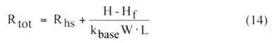
and kbase is the thermal conductivity of the heat sink base.
For purposes of illustration these equations were used to estimate heat sink thermal resistance for a 50 x 50 mm aluminum heat sink. The effect of increasing the fin height and the number of fins is shown in Figure 2 for a constant air velocity and in Figure 3 for a constant volumetric flow rate. In both cases it may be seen that there are limits to how much heat sink thermal resistance may be reduced by either increasing fin length or adding more fins. Of course to determine how a heat sink will actually perform in a specific application it is necessary to determine the air velocity or volumetric flow rate that can be delivered through the heat sink. To do this it is necessary to estimate the heat sink pressure drop characteristics and match them to the fan or blower to be used. This is a topic for consideration in a future article.
![]() |
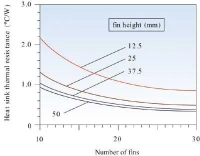
Figure 2. Effect of fin height and number of fins on heat sink thermal resistance at an air velocity of 2.5 m/s (492 fpm).
![]() |
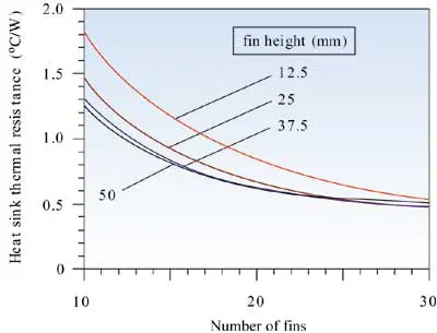
Figure 3. Effect of fin height and number of fins on heat sink thermal resistance at a volumetric air flow rate of 0.0024 m3/s (5 CFM).
References
- Teertstra, P., Yovanovich, M.M., and Culham, J.R., “Analytical Forced Convection Modeling of Plate Fin Heat Sinks,” Proceedings of 15th IEEE Semi-Therm Symposium, pp. 34-41, 1999.
Guys,
I’ve just ordered my new CPU cooler, and looking
for an exact explanation of how to calculate the heat dissipation area.
It was a bit longer than I expected, but this is a nice job at all! š
Cheers
WOW! Thank you so much! Great article, hope this reference is here to stay for a while.. gotta lotta calcs to do…
I am looking at your paper and calculations and have two related questions.
For Velocity through the fins paper shows calculation as:
V=G / (N_fin*b*Hf), this seems incorrect as number of channels for flwo is N_fin-1, so this would under estimate velocity
Conversly the thermal resistance of the heat sink is calculated as:
Rhs = 1 / (h*(Abase+Nfin*eta_fin*Afin) )
This means h is being applied to total fin area, but the outter 2 fins have outter surfaces that see unknown velocities.
As number of fins go to infinity second effect of using total fin area has diminesion impact, but the impact of the velocity calculation would increase as number of fins increase.
Not sure what is correct here.
Thanks
Joe
Joe,
Thank you for your comments/query regarding my article on āEstimating Parallel Plate-Fin Heat Sink Thermal Resistanceā in the February 2003 issue of Electronics Cooling. It is always pleasing to an author to learn of a reader that has given something you have written serious thought and you clearly have done so.
Your assertion that equation (7), which is V=G/(Nfin*b*Hf), would underestimate velocity is certainly true if all of the flow is ducted between the fins of the heat sink. For this situation, the appropriate calculation of average air velocity between the fins would be, V=G/((Nf-1)*b*Hf). However, if there is a gap between the outside fins of the heat sink and the adjacent walls of the duct, then the situation would change. If the gap on each side of the heat sink is equal to one-half the gap between the fins (i.e. b/2), then equation 7 would be an exact equation for the average value of V. If on the other hand, the gap on each side of the heat sink is greater than b/2, equation (7) would actually overestimate the average value of air velocity flowing between the fins.
You are also correct noting that in the article I applied the heat transfer coefficient (calculated using V from equation (7) in the Reynolds Number) to the total fin area of the heat sink which includes the two outside fin surfaces. Strictly speaking, this would only be correct if there is a gap (equal to b/2) allowing air flow on each side of the heat sink. But, as you commented and I agree, the effect of including the outer fin surfaces in the heat transfer calculations has a diminishing effect as the number of fins is increased.
However I do not agree that the impact of the velocity calculation would increase as the number of fins increase. For example, consider a tradeoff where the fin thickness (tfin) is held constant and the number of fins (Nfin) is varied. Then equation (7) becomes V1=G*(Nfin-1)/[Nfin*(W-Nfin*tfin)*Hf ]. On the other hand, basing the calculation strictly on the flow area between the fins equation (7) becomes V2= G*(Nfin-1) / [(Nfin-1)*(W-Nfin*tfin)*Hf]. Then the ratio of the velocity, V1, calculated by the one equation to the velocity, V2, calculated by the second equation is simply (Nfin-1)/Nfin , so as the number of fins increases the velocity calculated by the first equation approaches that calculated using the second equation.
I hope that this satisfactorily addresses your questions.
Regards,
Bob Simons
Thanks. It’s a great article simplifying calculations & consolidating all the data. I have one query. If Fins are at the both sides of heat sink base, (in your illustration it is at one side)should we consider thermal resistance of fins i.e. Rhs in parallel or in series? Also, in that case, will we have to multiply base thermal resistance by 2?
Kindly address my query asap as I am facing it in current project of mine.
Thank you.
Regards,
Rutuja
Dear Rutuja,
Thank you for your comment. Your question has been passed on to the author of this article, Robert Simmons.
Regards,
Electronics Cooling
Dear Mr. Bagul,
Thank you for your interest in and comments on my article in Electronics Cooling magazine on the subject of “Estimating Parallel Plate-Fin Heat Sink Thermal Resistance.”
I will be pleased to try to provide you an answer to the question you posed. However, before I attempt to do so, I would like to better understand the heat sink configuration you are looking at. Based upon your note, I visualize a heat sink with fins on both sides of a common baseplate (see figure). My question is how is the heat flowing, is it:1) from a warm air stream on one side through the heat sink to a cooler air stream on the opposite side; or 2) from a bottom plate into and up a shared baseplate and then out the two finned sides of the heat sink. A third possible configuration (not shown) is that of a heat source sandwiched in between the two finned sides with heat flowing to cooling airstreams on either side of the heat sink.
If you will can let me know what configuration best describes your situation I will get back to you.
Regards,
Bob Simons
Dear Mr. Simons,
First of all thank you very much for your reply.
Configuration no 2. i.e figure (b) drawn by you exactly describes arrangement of my heat sink.
I think thermal resistance of 3 components will come into play. these components are 1)Fins, 2)shared base plate & 3)bottom plate.
Am I right?
If I am, then how to calculate these? how to consider them, in series? or in parallel?
Thank You & Regards,
Ms. Rutuja Bagul š
Dear Mr. Simons,
I want to correct myself about configuration. configuration of my heat sink is a combination of two figures drawn by you. We can take heat sink where, air flow is as shown by arrow in configuration no 1) i.e. Figure (a), but heat flow is through the bottom plate (as shown in figure (b)); as heat generating device is mounted at bottom plate. I tried to attach an image file showing configuration and heat and air flow direction with my comment. But I couldn’t do so. I hope I have managed to clear the picture for you. Sorry for inconvenience. And thank you once again for your help.
Regards,
Rutuja Bagul
Dear Mr. Bagul,
Thank you for your most recent note, which was accompanied by the figure of the heat sink you are seeking to model. As is often said, āa picture is worth a thousand wordsā and your figure lives up to this statement. What you have is certainly more complex than I treated in my article on āEstimating Parallel Plate-Fin Heat Sink Thermal Resistanceā. In that article, heat was assumed to flow from the base plate uniformly into a set of parallel plate fins of uniform height. What you have is a base plate of non-uniform thickness with heat flowing from one end down the plate and out fins of varying height from the base. This is what I term a compound fin structure with a set of fins on a fin. The best way to model this would of course be with a Computational Fluid Dynamics tool (e.g. FloTHERM).
However there are some simple approaches you could take to estimate the overall thermal resistance of this heat sink structure. One would be to calculate the average fin height by summing up the height of all the fins from where they join the base plate, divide the total by the number of fins and use this average fin height to calculate a heat sink resistance (as described in my article) on each side of the base plate. These two resistances will be thermally in parallel, so the overall heat sink thermal resistance will be one-half of the thermal resistance of an individual side. Then you need to calculate a thermal conduction resistance along the base to where the heat source is attached. To do this, calculate an average thickness of the base (t) which you might do by adding the maximum thickness of the base to the minimum thickness and dividing by 2. You will also need to calculate an effective thermal conduction length (Leff) which you could do by taking the total width of the base (as shown in your front view) from the left end to the heat source at the right end and divide by 2. The effective thermal conduction resistance would then be Rcond = Leff/(Kmatl x Acs), where Acs is the product of the effective base thickness, t, and the overall length of the heat sink in the air flow direction (as shown in your side view). Then add the overall heat sink resistance to the effective thermal conduction resistance to obtain the total thermal resistance from where the heat source is attached to the heat sink out to the cooling air.
As I implied above, there are some other ways that the problem could be approached, short of going to a CFD tool. However, they are more complicated than I could go adequately describe in a brief note. Perhaps they could be the topic of a future ElelectronicsCooling article. In any event, I hope my response to your query helps. Also, remember these are approximate methods at best and results should always be confirmed by test before any product application.
Regards,
Bob Simons
Would the velocity and/or the calculations be different, if the heat sink had the fins pointing down? Typically, when we mount our amplifiers to the heat sink, the orientation of the heat sink has the fins pointing down.
Hi Darrel,
Thank you for your comment. Your question has been passed on to the author of this article, Robert Simmons.
Regards,
Electronics Cooling
Darrel,
Thank you for your interest in my article on “Estimating Parallel Plate-Fin Heat Sink Thermal Resistance” and I am sorry that I did not get a chance to respond to your query sooner. In general, as long as you are utilizing forced convection heat transfer (i.e. a fan or similar air moving device is providing a forced air flow through the fin passages), whether the fins are pointing up or down should make no difference.
It is when you are depending upon a buoyancy driven flow (i.e. natural convection heat transfer) that the orientation of the fins (i.e. up or down from the baseplate can have a significant effect on heat transfer. Of course, the convective heat transfer relationships used in my article would not apply in the case of natural convection anyway.
Regards,
Bob Simons
Thanks for the reply. So, it looks like I will have to find another model for natural convection. I need two models; one for natural convection and one for forced convection.
I am fascinated by the discrepancy of the Reynolds number between this method above, and the similar method you put forward for calculating pressure drops (found on a different page on this site). I calculate extremely low values for Reynolds numbers (~1.5) using the above equation, whereas I get much higher Reynolds numbers using standard narrow channel flow (~250), and that found in your pressure drop method. Can you shed some light on the discrepancy?
In any case I appreciate you putting these up online.
I also ran into the same issue as Kurt. Why are the Reynolds number differs so much from this method and pressure drop method??
Hi Ben,
You question has been passed on to the author of this article, Robert Simons.
Regards,
Electronics Cooling
This is an amazing explaination on the aspects of fluid-thermodynamics, however how would the formula change if there was no airflow. I guess air would flow by means of from area of heat to area of cold intrinsically. If a heat sink was oriented vertically, such that, hot air would rise out between the fins, how would one then be able to calculate the thermal resistance of a heatsink such as this in no air movement? Obviously it would be a lot higher (meaning it would not be able to remove as much heat), but how does one estimate what it would be given the lovely formula’s above? š