
Thermal simulation of electronic systems using FloTHERM usually involve the definition of the 3D geometry and relevant material properties, specification of the power dissipation of the components as well as the ambient temperature that together lead to a numerical prediction of the resulting heat fluxes and temperatures. If the predicted component temperatures are too high then you’ve got a problem. Actually, as a FloTHERM user once said, by using FloTHERM there aren’t any thermal problems anymore, just challenges as to how to (re)design the system to achieve compliant component temperatures. As far as the governing equations of heat transfer are concerned the relationship between power dissipation and temperature (rise) is bi-directional, just because we consider power to be the input and temperature to be the output, there’s no reason FloTHERM has to be bound by that. Just as well because more often than not the maximum component temperature limit is known but an accurate value of component power dissipation is not.
From what little I’ve learnt about the wonderful world of overclocking the use of sub-zero methods of cooling (e.g. liquid nitrogen or dry ice (‘dice’) cooled CPU/GPU mounted pots) are great party or demo pieces but not often employed on a day to day basis. The use of heatsinking and closed loop liquid cooling systems is more common. Either way, overclocking involves the ramping up of processor speeds that results in an increase is component power dissipation that would result in excessive component temperatures (and resulting operational failure) if the extra heat were not to be removed effectively enough. I’m personally not that au fait with the relationship between processor speed and power dissipation. One relationship I am aware of is that CPU power consumption = Capacitance x Voltage squared x Frequency. But that doesn’t include leakage current losses. Short of having access to electrical engineers doing full processor system simulations your thermal engineer will normally just be given a maximum assumed power dissipation, or a TDP (thermal design power). Resulting simulations may therefore tend to overestimate the resulting junction or case temperatures.
OK, let’s flip things round and ask ‘what would the power dissipation be to achieve a junction temperature = maximum rated junction temperature for a given cooling solution?’. Something FloTHERM excels at answering! For you FloTHERM users out there say using a detailed component model with a source attribute used to define the power, set a fixed temperature source option instead of the usual power dissipation option. Once the model is solved, [View/Top] the cuboid used to represent the die and look in the ’solid conductors’ table. Hey presto, the total power dissipation is shown. As a double check you could enter that power dissipation instead of the fixed temperature resolve and you’ll find the junction temperature = maximum value you entered in originally. Sure, you could use the Command Center to find the same thing using multiple ‘what if’ simulations but this method is direct.

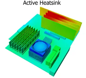
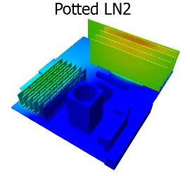
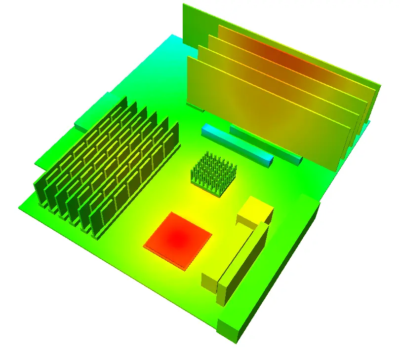
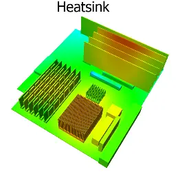
Back to overclocking. Using this fixed temperature approach (where I set the CPU Tj = Tj_max = 90degC) I simulated 4 different cooling configurations; no heatsink, a passive heatsink, an active heatsink (+fan) and a LN2 cooled pot. There’s quite a bit of activity in LN2 or dice pot design. The use of holes drilled into the base or rods on the base surface both increase the cooling area, turning them more into liquid cooled heatsinks. The following images all have the same colour temperature range going from 20degC to 90degC. Anything blue is at or below 20degC. Nothing will be above 90degC as that is an input.


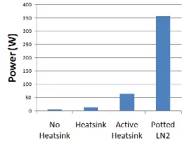 Here’s a chart showing the resulting power dissipations that are achievable under those cooling conditions. The LN2 sub-zero cooling allows for a power dissipation about 6 times that of the (standard) active heatsink cooling approach. Assuming that the CPU voltage has not been altered that would equate to an x6 increase in clock speed as a theoretical maximum. It’s at this stage where I have to admit to some deficiencies in this entire approach when trying to emulate ‘reality’… A steady state assumption is made where the CPUs operation is such that the entire die reaches a steady and uniform temperature, is this possible to achieve in reality? I doubt it. It’s also not just absolute temperatures that result in failure. Temperature gradients drive thermo-mechanical stresses that result in package damaging strains. The gradients when going from a fixed die temp of 90degC to an LN2 temperature of -196degC are massive, the system would likely fail long before that state was reached. Maybe an overclocker would like to comment on what maximum junction temperatures can usually be reached under sub-zero cooling conditions. Also, how accurate actually is the on-die temperature monitoring system under such conditions? Anyway, if asked the question ‘how much better is LN2 cooling compared to normal active heatsink cooling’ maybe the answer could be ‘about 6 times better, max, maybe’.
I love examining predicted heat fluxes to get a feel as to where the heat is flowing, is it getting out of the system quickly and easily, is it encountering any specific thermal bottlenecks that could be relieved? Using the new ‘heat flux particle animation’ feature in the latest release of FloTHERM, V9.2, you can animate these heat flow paths. Here are what they look like for the 4 cooling configurations.
With no heatsink the heat has to flow down into the PCB, encountering all the thermal resistances the PCB has to offer, or trickle out of the package top. You can’t shove much heat that way without going above Tj_max, in fact you can onyl shove about 6W. With a heatsink the heat conducts up into the fins and then out through the air that moves slowly only due buoyancy. A bit better, but not much. Place a fan on the heatsink and the heat is positively sucked up the fins then blown back down through the fin channels. Put a sub-zero copper pot on top and the heat is has no option but to rush up towards the LN2 at the upper face of the pot base, the Formula 1 of cooling systems.
13th June 2011, Seoul.

