
Introduction
The advancement of artificial intelligence (AI) has led to an accelerating development of high-performance AI chips, which are increasingly characterized by ultra-large die areas, extreme interconnect density, and high-power consumptions. Heat dissipation is a bottleneck for the next-generation high-power graphics processing unit (GPU) and necessitates advanced thermal management solutions [1].
While the reliable operating temperature limit is 80°C [1], the power map is generally not uniform and the peak heat flux can reach ~ 1 kW/cm² [2]. Recently, direct on-chip cooling is gaining attention among researchers due to improved thermal performance and its potential to reduce the need for thermal interface make this materials (TIMs) [3].
Among various on-chip cooling solutions, coolant impingement using distributed inlets and outlets microjet configuration can dissipate high heat flux and ensure nearly uniform temperature distribution.
This method enables direct fluidic interaction with heat-generating components, shorter fluid paths and uniform distribution. Therefore, manifold design plays a critical role in the overall thermo-hydraulic performance of such liquid cooling systems.
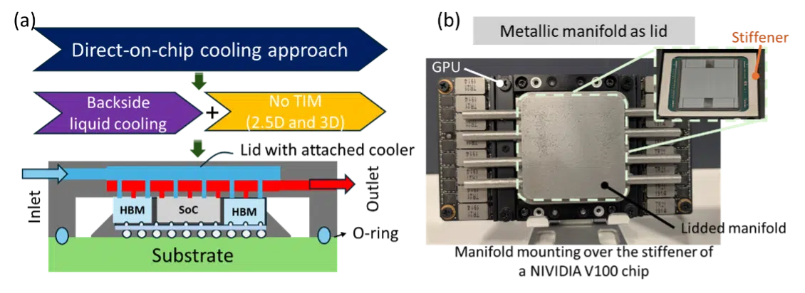
In recent years, high-power AI chips are usually packaged in a lid-less configuration, which greatly complicates thermal management and requires new and innovative cooling concepts to dissipate heat generated during operation. Also, these chips include a stiffener ring around the perimeter of the package to provide mechanical stability, maintain package flatness, and serve as a platform for the cooling solutions.
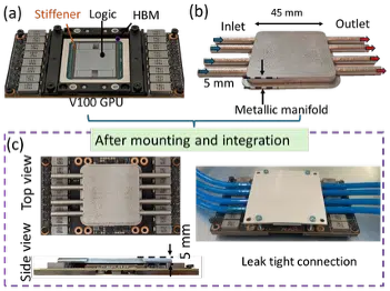
In this regard, the authors have proposed a lid-compatible manifold with distributed liquid jet impingement for direct-on-chip cooling, see Figure 1(a-b). This utilizes both the advantages of on-chip cooling for enhanced thermal performance and mechanical robustness solutions of lidded packages.
TSMC has demonstrated the ability to dissipate a thermal load over 3 kW at a flow rate over 10 LPM using water as the coolant and on-silicon cooling solution [4]. Abundant availability with outstanding thermal qualities makes DI water a favorable choice for liquid cooling.
Lidded-Manifold Concept Design
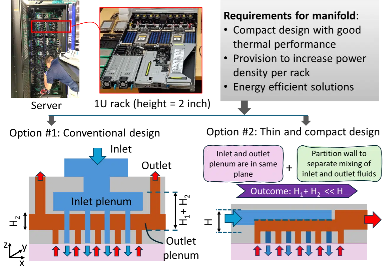
In the digital economy, driven by large data volumes, artificial intelligence, and high-performance computing, increasing power density per rack is an obvious need for data centers [6].
Since increasing computing per unit volume necessitates reducing the physical size of the hardware, a 1U server with only 2 inches (50.8 mm) of vertical height offers the lowest common form factor, allowing for higher compute density within the rack. This imposes a strict space constraint on the thermal management solutions to reduce overall dimension, especially in the z-direction.
The conventional multi-liquid jet configuration has two separate plenums for inlet liquid and outlet liquid, which makes the overall design quite bulky. Also, lateral feeding to the manifold is required to make it more appealing for high-density computing environments.
In this regard, a novel manifold design can be used to integrate the inlet and outlet plenum into a single plane, where inlet and outlet liquids can be separated with a partition wall, see Figure 2 [5].
In this way, the overall dimension of the manifold can be drastically decreased. For electronics cooling applications, a metallic manifold is preferred over any non-metallic solutions as the former has high durability, excellent chemical resistance, and offers good mechanical properties [7].
Numerical Design of Lid Compatible Metallic Manifold
Multijet nozzle cooling, with cooling unit cell arrays including locally distributed inlets and outlets, has been fundamentally understood and experimentally demonstrated for the scalability of the nozzle array, from small chips to multichip area [8].
Therefore, to experimentally characterize the thermal and hydraulic performance of this compact manifold design concept, a small footprint lateral manifold with heat source area of 10 mm × 10 mm is demonstrated, keeping the overall height of 5 mm, with water used as the working fluid in this study.
Enjoying this article?
Subscribe to Electronics Cooling for practical, engineer-focused insight on today’s thermal management challenges—plus immediate access to new digital magazine issues.
Subscribe here →
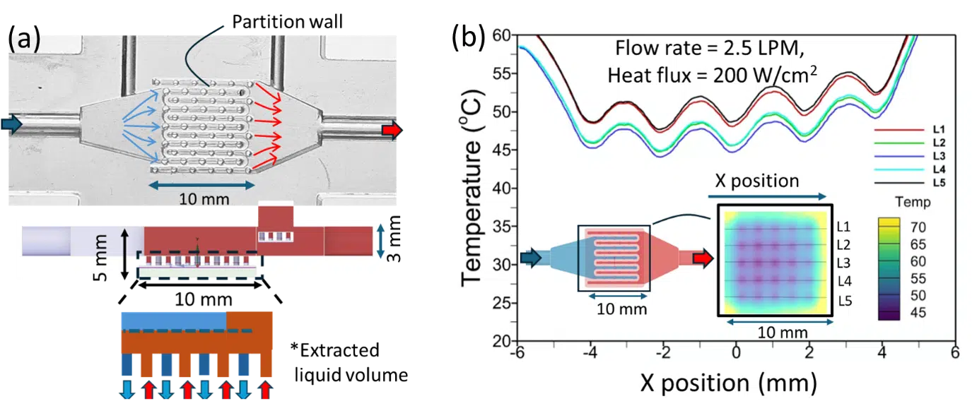
The compact lateral feed manifold has one inlet and one outlet for flow connections. The orifices of the inlet and outlet are kept at 0.6 mm (total of 25) and 0.5 mm (32), respectively, refer to Figure 3(a).
The partition wall is 0.4 mm thick with a 3 mm height. The heater has a thickness of 0.2 mm, with impinging area of 10 mm × 10 mm. A single-phase numerical simulation is performed to understand intrinsic coupling of flow distribution and thermal performance. It is noted that this design has a unit cell size of 2 mm.
The chip surface temperature profile is plotted for a flow rate of 2.5 LPM, inlet fluid temperature of 20°C and heat flux of 200 W/cm2, see Figure 3(b). The surface temperature uniformity is investigated by measuring temperature variation of five liquid impingement rows over the heated surface from inlet to the outlet.
The chip temperature is always maintained between 45°C and 70°C, which is well below the reliability temperature limit of silicon electronics. Next, the thermal performance of the current design is experimentally studied for various boundary conditions.
Experimental Characterizations of a Lid Compatible Metallic Manifold
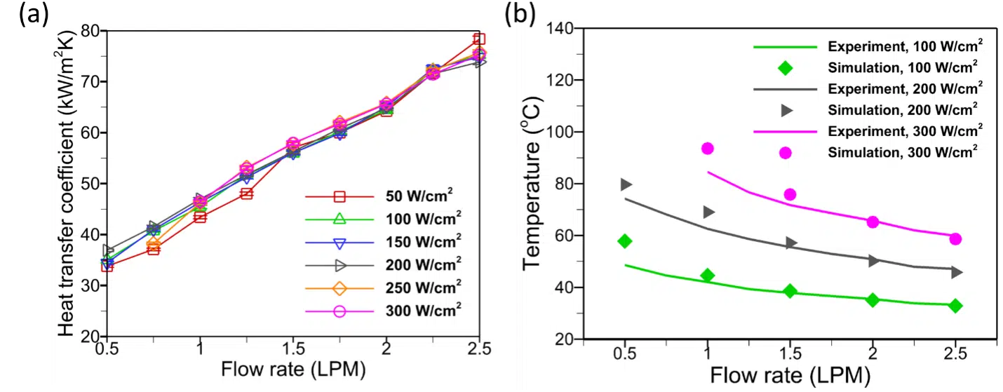
In the high-power AI chips applications, heat flux at the maximum thermal design power (TDP) may reach up to ~200 W/cm2. The heat transfer coefficient (HTC), which is a measure of heat dissipation performance, is plotted for various experimental conditions of flow rate and heat flux, with water as the working fluid, see equation 1.
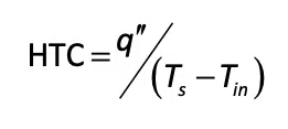
Where, q”, Ts, Tin is heat flux, surface temperature and inlet fluid temperature, respectively. The HTC is calculated to be 80 kW/m2K at a flow rate of 2.5 LPM, which translates to a very low thermal resistance of ~0.1 K-cm2/W, see Figure 4(a).
The HTC is shown to increase with a rise in flow rate, which is typical for single-phase operations. The surface temperature surpasses 80°C at a heat flux of 300 W/cm² when the flow rate decreases below 1.25 LPM, emphasizing the importance of flow rate in maintaining high heat load operation.
Also, the average temperature at steady state is compared to the numerical model and shows a good match, Figure 4(b). This demonstrates the effectiveness of the current thermal management solutions with a small form factor for high-power AI chips.
Demonstration of Lid Compatible Metallic Manifold
To demonstrate feasibility of the lid-compatible manifold design, a metallic manifold was 3D printed, with stainless steel 316 material as per the requirements of NVIDIA V100 GPU dimensions. The logic and HBMs are of different sizes, measuring 26 mm × 30 mm and 8 mm × 12 mm, respectively [9].
The power map is substantially different, with logic dissipating the most power. Therefore, the design must include a higher number of liquid inlets in the logic compared to the HBMs. Also, for other high-power GPU architectures, one must consider the orientation and dimensions of the logic and HBMs.
The stiffener provides structural rigidity and a platform to integrate the metallic manifold to rest over it. In order to make it leak proof, an O-ring or gasket sealing can be utilized. Therefore, the manifold design must facilitate holding the O-ring/gasket sealing and eventually rest over the stiffener of the GPU.
Additionally, a top cover plate and screw arrangement can be utilized to provide a uniform mechanical compression between the manifold and GPU. In this setup, the flow loop is connected to four intake and four outlet tubes, two of which are for HBMs.
There is also a provision in place to ensure that connection tubes do not encounter any other GPU peripheral components.
Summary
To increase power density per server, a compact and small form factor cooling solution is desired. In this regard, a lid-compatible manifold with distributed inlets and outlets design is demonstrated on an actual NVIDIA V100 chip.
Combining the inlet and outlet plenum in a single plane results in a significant reduction in the overall height of the manifold, measuring 5 mm for the current design. The integration of the current design is simple and easy; it needed to be mounted over the stiffener through the support of an O-ring for a leak-free operation.
Additionally, thermo-hydraulic performance is studied for a similar manifold design with a smaller evaporator area of 10 mm × 10 mm. A significantly higher heat transfer coefficient was obtained measuring 80 kW/m2K at a flow rate of 2.5 LPM and heat flux of 300 W/cm2.
The surface temperature was always below 80°C for flow rates greater than 1.25 LPM. Continued work on the lidded manifold aims to dissipate a thermal load of ~ 1000 W. Experimental testing using a dielectric fluid (R1233zd(E), Honeywell™) is undertaken at a thermal design power (TDP) of 300 W at various flow rates to understand thermal performance.
Results will be communicated soon. Ultimately, this design provides excellent cooling solutions with mechanically robust solutions, which are required for next-generation AI chips.
References
[1] P. De Bock, T. Bress, V. Lecoustre, A. Gidwani, and C. Noyes, “Data Center Energy Reduction by Lowering Chip-to-Supply Thermal Resistance,” in 2023 22nd IEEE Intersociety Conference on Thermal and Thermomechanical Phenomena in Electronic Systems (ITherm), Orlando, FL, USA: IEEE, May 2023, pp. 1–6. doi: 10.1109/ITherm55368.2023.10177591.
[2] T. Wei et al., “Experimental and Numerical Study of 3-D Printed Direct Jet Impingement Cooling for High-Power, Large Die Size Applications,” IEEE Trans. Compon. Packag. Manuf. Technol., vol. 11, no. 3, pp. 415–425, Mar. 2021, doi: 10.1109/TCPMT.2020.3045113.
[3] T. Wei, All-in-one design integrates microfluidic cooling into electronic chips, Nature, News and Views, 585, 188-189 (2020) doi: 10.1038/d41586-020-02503-1, 2020.
[4] Y.-J. Lien et al., “Direct-to-Silicon Liquid Cooling Integrated on Cowos® Platform,” in 2025 IEEE 75th Electronic Components and Technology Conference (ECTC), Dallas, TX, USA: IEEE, May 2025, pp. 743–747. doi: 10.1109/ectc51687.2025.00131.
[5] G. Sahu, R. Li, K. Yogi, A. Hetal Patel, and T. Wei, “Experimental Investigation of a Compact Lid-Compatible Multijet Impingement Manifold for Direct-On-Chip Cooling,” IEEE Trans. Compon. Packag. Manuf. Technol., vol. 15, no. 4, pp. 748–756, Apr. 2025, doi: 10.1109/TCPMT.2024.3506943.
[6] S. K. Rajan, A. Kaul, T. E. Sarvey, G. S. May, and M. S. Bakir, “Monolithic Microfluidic Cooling of a Heterogeneous 2.5-D FPGA With Low-Profile 3-D Printed Manifolds,” IEEE Trans. Compon. Packag. Manuf. Technol., vol. 11, no. 6, pp. 974–982, Jun. 2021, doi: 10.1109/TCPMT.2021.3082013.
[7] A. Pappaterra, B. Vandevelde, M. Nazemi, W. Verleysen, and H. Oprins, “Advanced (Metal 3D-Printed) Direct Liquid Jet-Impingement Cooling Solution for Autonomous Driving High-Performance Vehicle Computer (HPVC),” in 2021 22nd International Conference on Thermal, Mechanical and Multi-Physics Simulation and Experiments in Microelectronics and Microsystems (EuroSimE), St. Julian, Malta: IEEE, Apr. 2021, pp. 1–14. doi: 10.1109/EuroSimE52062.2021.9410838.
[8] T. Wei et al., “Experimental and Numerical Study of 3-D Printed Direct Jet Impingement Cooling for High-Power, Large Die Size Applications,” IEEE Trans. Compon. Packag. Manuf. Technol., vol. 11, no. 3, pp. 415–425, Mar. 2021, doi: 10.1109/tcpmt.2020.3045113.
[9] G. Sahu, D. Hoang, R. Li, A. H. Patel, K. Yogi, and T. Wei, “First Demonstration of Metal-Lidded Integral Microjet Impingement on-Chip Cooling Structures with Alternating Feeding and Draining Nozzles for High-Performance Interposer Packages,” in 2025 IEEE 75th Electronic Components and Technology Conference (ECTC), Dallas, TX, USA: IEEE, May 2025, pp. 499–504. doi: 10.1109/ectc51687.2025.00088.

