Introduction
The introduction of large language models (LLM), such as ChatGPT, has made artificial intelligence highly accessible. One of the key driving forces behind this growth has been the advancement in the processing power of compute devices such as central processing units (CPUs) and graphics processing units (GPUs).
An increase in this processing power is accompanied by an increase in the dissipated thermal power. Recently announced devices, such as NVIDIA’s Blackwell B200 and AMD’s Instinct MI300A, dissipate more than 700 W confined in a footprint that can fit in the palm of an adult hand. Most of these devices also have very stringent requirements on the maximum chip backside temperature, typically < 90°C.
The small form factor, large power dissipation and strict temperature requirement makes thermal management of these devices challenging and critical for sustained maximum compute performance and reliability. Additionally, power consumption at the rack level is projected to reach close to 600 kW per rack in the near future [1]. Air and single-phase liquid cooling solutions may not be adequate at these power densities [2].
Two-phase cooling takes advantage of the latent heat of vaporization by boiling the coolant in a heat sink and can provide several times greater heat carrying capacity than single-phase cooling technologies. Refrigerants, especially ones that offer low global warming potential (GWP), are an attractive candidate for these applications. In addition to effective cooling, they prevent biological growth and corrosion, and their dielectric nature mitigates risks to electrical components from fluid leakage [3].
It is desirable to operate the two-phase heat sinks at elevated saturation temperatures (Tsat) for efficient heat rejection and possible waste heat recovery. For refrigerants, this translates to saturation pressures several times higher than atmospheric pressure.
Microchannel based heat sinks are suitable for such applications as they provide high mechanical strength and surface area in a compact form factor, and can be fabricated at scale. Simulation tools that can predict the thermal and mechanical performance of such heat sinks can help generate optimized heat sink designs. However, there is a lack of suitable tools given the complexity of the modeling framework.
Nokia Bell Labs (NBL) has developed a steady-state simulation framework to tackle the challenges of designing a two-phase microchannel heat sink. The framework incorporates two simulators. The first one is a stand-alone NBL two-phase simulator that utilizes well known correlations to obtain the streamwise, two-phase heat transfer coefficient (HTC) and pressure distribution in a rectangular microchannel.
For simplicity, the simulator analyzes a single 2D microchannel and can achieve convergence in a few seconds. Details on this simulator and experimental validation of its predictive capabilities can be found in Ref. [4].
This simulator can be utilized to quickly explore a large design space under a wide range of inlet flow conditions and working fluids. The second simulator integrates this NBL two-phase simulator with ANSYS Mechanical through PyAnsys package [5] and thus, enables simultaneous thermal and mechanical analysis of mul-tichannel 3D heat sink geometries.
Moreover, this integrated simulator equalizes pressure drop among the microchannels by performing iterative flow redistribution. This allows it to predict flow and temperature distributions related to complex non-uni-form heat maps, including hot spots. The details of this simulation framework have been presented in Ref. [6].
The presented work utilized this framework to compare the effects of microchannel width, inlet flow conditions, hot spots, and three refrigerants: R134a (GWP of 1430), R1234ze(E) (GWP of 6), and R1233zd(E) (GWP of 1) on a copper heat sink dissipat-ing 8.8 W/cm2 at inlet saturation temperature, Tsat = 60°C. These simulations use two-phase correlations by Kim and Mudawar [7].
Design Parameters for Microchannel Heat Sink
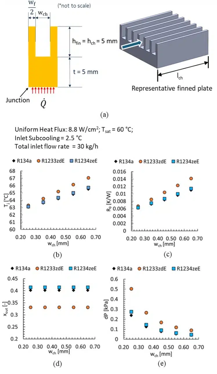
The microchannel heat sink in this work consists of a copper finned plate incorporating straight rectangular fins, and a copper cover plate that houses plenums for coolant distribution. The gap between two consecutive fins constitutes a microchannel with a width, height and length of wch, hch and lch, respectively, and a fin thickness of wfin (Figure 1).
In this work, the footprint of the finned plate was fixed at 75 mm × 75 mm, which is representative of commercial high-power devices announced in recent years, and “junction” refers to the base of the plate. Additionally, wch = wfin, hch = 5 mm, and lch = 75 mm in all cases. The cover plate has been omitted in the thermal-flow analysis while included for the structural analysis.
Enjoying this article?
Subscribe to Electronics Cooling for practical, engineer-focused insight on today’s thermal management challenges—plus immediate access to new digital magazine issues.
Subscribe here →
Effect of Microchannel Width
Increasing wch from 0.25 to 0.75 mm, while keeping other parameters fixed, led to higher junction temperature, Tj (= average temperature at the junction of the microchannel), and thermal resistance, Rθ (defined as (Tj–Tsat)/dissipated thermal power), while the pressure drop, dP, decreased. The increase in Tj as wch increased primarily resulted from the reduced heat sink surface area, while the increasing microchannel cross-section area decreased dP.
A large reduction in dP was observed when wch increased from 0.25 mm to 0.45 mm. Further increases in wch led to smaller improvements in dP while Tj scaled linearly. Thus, wch = 0.45 mm, with Rθ <= 0.01 W/mK and dP < 0.2 kPa for the three refrigerants, was selected for further analysis.
In all cases, R134a offered the lowest Tj, Rθ, and dP, closely followed by R1234ze(E), while R1233zd(E) led to the lowest exit quality, xout.
Effect of Inlet Conditions
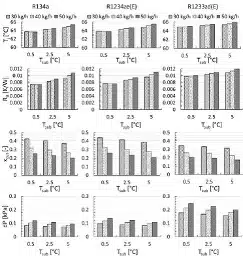
Figure 2 shows the impact of working fluid and inlet flow conditions on the performance of a microchannel with wch = 0.45 mm at heat flux, q”= 8.8 W/cm2, and inlet Tsat = 60°C. Both Tj and Rθ showed very little variation with total flow rate, ṁ, at low inlet subcooling, Tsub = 0.5°C, but increased with ṁ for higher Tsub = 2.5 and 5°C. An increase in Tsub and ṁ delays the transition of the single-phase subcooled liquid to two-phase.
The resulting low single-phase HTC near the inlet region leads to locally high heat sink temperatures, thus, increasing the average Tj and Rθ. At Tsub = 0.5°C, the change in single-phase length with ṁ was small and thus, Tj and Rθ remained relatively constant compared to cases with higher Tsub. Additionally, with ṁ fixed, the delayed flow transition to two-phase with increasing Tsub led to reduced xout and hence, dP.
On the other hand, at a fixed subcooling, dP increased with ṁ despite lower xout, primarily due to higher frictional losses caused by the increased flow velocity within the channel. Thus, low Tsub and ṁ at the heat sink inlet is desirable, if xout can be maintained below incipient dryout levels. On changing the refrigerant from R134a, Rθ increased by < 5% for R1234ze(E), and 11-37% for R1233zd(E).
Furthermore, the higher liquid-to-vapor density ratio of R1234ze(E) (14.7) and R1233zd(E) (56.6) compared to R134a (12), led to a 15% and 200% increase in dP respectively. Overall, R134a and R1234ze(E) had similar thermal-hydraulic performance, and both surpassed R1233zd(E) in these metrics.
Multichannel 3D Heat Sink – Effect of Hot Spots
The above results were obtained by assuming a uniform q” and absence of flow maldistribution among the heat sink microchannels. In real-world applications, however, such conditions rarely exist. The chip backside heat map typically includes localized high heat flux regions called hot spots.
Hot spots can trigger flow maldistribution and increase the risk of dryout in nearby channels. However, these multichannel hot spot effects are difficult to capture using the single-channel simulation approach discussed up to now, underscoring the importance of the developed multichannel approach.
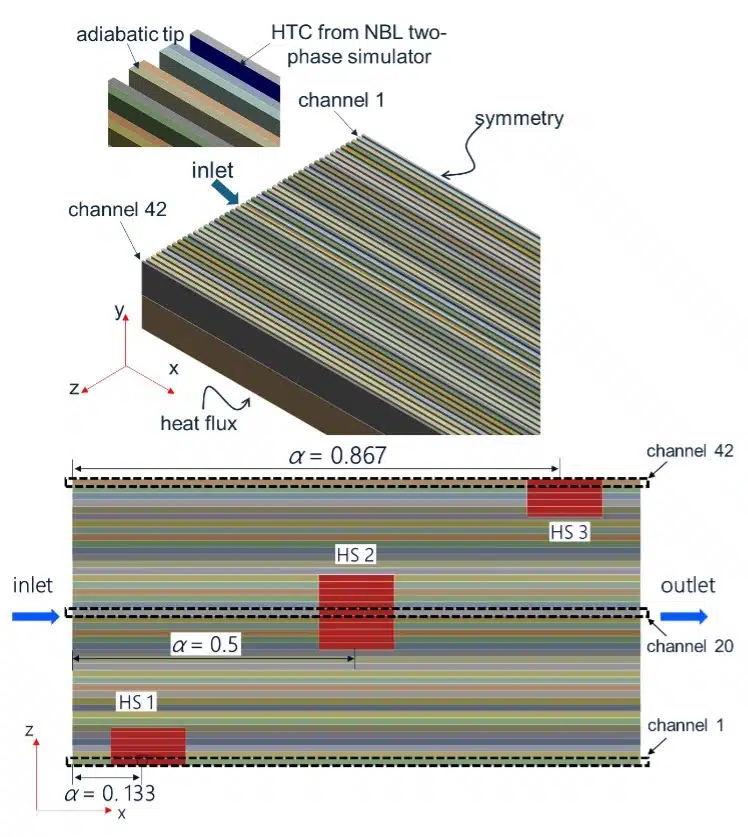
For these multichannel simulations, a 3D model of a 75mm × 75 mm finned plate was generated with wch = wfin = 0.45 mm, and hfin = 5 mm (Figure 3). Three staggered hot spots, each with q” = 50 W/cm2, were implemented at the junction of the evaporator. The heat sink inlet condition was defined with total ṁ = 40 kg/h, Tsat = 60°C and Tsub = 2.5°C for the three refrigerants. Only half of the symmetric finned plate was analyzed to reduce model complexity.
Figure 4(a) shows the calculated temperature distribution using R134a, however, these observations hold for other refrigerants as well. Given the high subcooling, the inlet regions of the micro-channels showed higher temperature due to the low single-phase HTC. The upstream hot spot, HS1, was located directly beneath this region, and hence, showed the highest temperature. Once the flow transitioned to two-phase, the heat sink temperature decreased, with local maximums at HS2 and HS3.
Additionally, to highlight the differences between multichannel and single-chan-nel prediction approaches, channels 1, 20, and 42 (located above HS1, HS2, and HS3, respectively, as shown in Figure 3) were iso-lated from the multichannel model and simulated individually as single channels with corresponding hot spot intensity and location.
As shown in Figure 4(b), the multichannel simulation predicted up to 1.9% lower Tj and 12-19% lower xout for 1st, 20th, and 42nd channels compared to the values from corresponding single channel analysis.
This is because the multichannel analysis considered lateral heat spreading in the plate, which reduced hot spot intensity and channel thermal load. Effective heat spreaders, such as those under development at NBL [8], [9], can further mitigate the effects of such hot spots.
Moreover, the results indicated that HS1 aided an early transition to two-phase flow, increasing xout and flow resistance, and thereby reducing the flow rate in nearby channels (Figure 4(c)).
Hence, HS1 was more detrimental to the performance compared to the downstream located HS2 and HS3. Once again, R134a and R1234ze(E) showed better thermal performance than R1233zd(E).

Static Structural Analysis – Effect of High Saturation Pressure
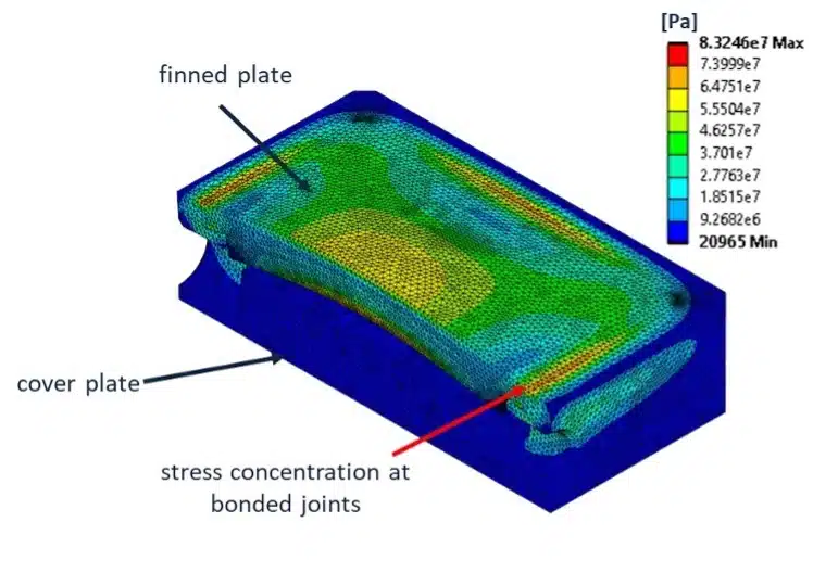
Refrigerants R134a and R1234ze(E) have high saturation pressures, especially when operating at elevated coolant temperatures (16.6 atm and 12.6 atm, respectively, at 60°C). It is essential to minimize deformation in the heat sink while minimizing the thickness of the finned plate to achieve low thermal resistance even at such high operating pressures. The integrated simulator performs steady state structural analysis to identify critical areas with high stress concentrations on the heat sink.
Figure 5 shows these regions for the symmetric half of a heat sink made with 75 mm × 75 mm finned plate with wch = wfin 0.25 mm and using R134a at Tsat = 60°C. The stress concentration was observed to be highest in the brazed joints, followed by the center of the finned plate. Comparing results from the three refrigerants, the margin of safety (defined using 10% derated ultimate strength of copper) was 3, 3.9, and 11.5 for R134a, R1234ze(E) and R1233zd(E), respectively.
Here, R1233zd(E) demonstrated a clear advantage over the other high-pressure refrigerants. Despite reduced thermal performance, the higher margin of safety for R1233zd(E) directly translates to a thinner finned plate, lower material costs, and higher coolant temperatures for efficient waste heat rejection and recovery.
Thus, R1233zd(E) was selected for further experimental characterization of developed heat sinks and the results are discussed in [10], [11].
Conclusion
An in-house developed two-phase simulation framework was utilized to study the effects of channel width, inlet flow rate and subcooling, three refrigerants, and a staggered hot spot configuration on microchannel heat sink performance. The thermal performance degraded while pressure drop improved with increase in wch.
For a given ṁ, low inlet Tsub led to improved Rθ and dP. Among the refrigerants, R134a exhibited the best thermal-fluid performance, however, it has very high GWP and is being phased out due to environmental considerations.
On the other hand, R1233zd(E) exhibited low outlet quality and reduced mechanical stresses, allowing thinner finned plates, reduced material costs, and higher operating temperatures.
References
[1] “1,000 homes of power in a filing cabinet – rising power density disrupts AI infrastructure.” Accessed: July 17, 2025. [Online]. Available: www.goldmansachs.com/insights/articles/rising-power-density-disrupts-ai-infrastructure
[2] A. Heydari, “HIGH HEAT DENSITY SINGLE- AND TWO-PHASE COOLING OF DATA CENTERS,” Dec. 13, 2021. [Online]. Available: www.arpa-e.energy.gov/sites/default/files/migrated/5.%20Ali_ARPA-E-Presentation-12-13-21-Final-Released.pdf
[3] D. L. Saums, S. Gill, T. Louvar, D. Engineer, and A. Sathe, “Semiconductors for Vehicle Powertrains Vaporizable Dielectric Fluid Cooling of IGBT Power Semiconductors for Vehicle Powertrains”.
[4] Q. Wu and T. Salamon, “Two-phase thermofluidic modeling and validation of a multi-zone microchannel evaporator,” in 2022 21st IEEE Intersociety Conference on Thermal and Thermomechanical Phenomena in Electronic Systems (iTherm), May 2022, pp. 1–10. doi: 10.1109/iTherm54085.2022.9899499.
[5] “PyAnsys — PyAnsys.” Accessed: Dec. 28, 2023. [Online]. Available: www.ocs.pyansys.com/version/dev/
[6] S. N. Parbat et al., “An Integrated Simulation Framework for Thermal-Mechanical Performance Analysis of Two-phase Microchannel Evaporators,” in 2024 23rd IEEE Intersociety Conference on Thermal and Thermomechanical Phenomena in Electronic Systems (ITherm), Aurora, CO, USA: IEEE, May 2024, pp. 1–10. doi: 10.1109/ITherm55375.2024.10709519.
[7] S.-M. Kim and I. Mudawar, “Universal approach to predicting saturated flow boiling heat transfer in mini/micro-channels – Part II. Two-phase heat transfer coefficient,” Int. J. Heat Mass Transf., vol. 64, pp. 1239–1256, Sept. 2013, doi: 10.1016/j. ijheatmasstransfer.2013.04.014.
[8] R. Roy, S. Parbat, and T. Salamon, “Dependence of Oscillation Frequencies on Operating Conditions in an Oscillating Heat Pipe,” in 2024 23rd IEEE Intersociety Conference on Thermal and Thermomechanical Phenomena in Electronic Systems (ITherm), Aurora, CO, USA: IEEE, May 2024, pp. 1–6. doi: 10.1109/ITherm55375.2024.10709589.
[9] S. Faisal et al., “Experimental investigation of the heat spreading performance of oscillating heat pipes for electronics cooling applications,” in 2024 23rd IEEE Intersociety Conference on Thermal and Thermomechanical Phenomena in Electronic Systems (ITherm), Aurora, CO, USA: IEEE, May 2024, pp. 1–6. doi: 10.1109/ITherm55375.2024.10709412.
[10] D. J. Apigo et al., “Experimental characterization of a low thermal resistance microchannel heatsink utilizing low GWP refrigerant for high power GPU applications,” presented at the 2025 24th IEEE Intersociety Conference on Thermal and Thermomechanical Phenomena in Electronic Systems (ITherm), Dallas, Texas, May 2025.
[11] Y. Liu et al., “Experimental Demonstration of High-Power Thermal Test Vehicle for Two-Phase Cooling for AI Datacenters, 5G RAN, and EDGE Compute Nodes,” presented at the ECTC, Dallas, Texas, May 2025.

