Abstract
This paper presents a novel thermal management approach for power semiconductor modules by integrating active liquid cooling directly into the substrate. Utilizing Direct Bond Copper (DBC) structures embedded within liquid cold plates, the method minimizes thermal interfaces, improves power density, and ensures better reliability. It contrasts traditional multi-interface cooling paths with an integrated monolithic solution that embeds the coolant flow directly under the semiconductor die using proven manufacturing techniques.
Introduction and Motivation
The push toward electrification across transportation — rail, marine, aviation, and ground vehicles — brings significant benefits such as lower emissions, quieter operation, and reduced dependency on fossil fuels. However, it also places higher demands on power electronic systems, requiring efficient thermal management to handle increasing power densities. Emerging wide-bandgap semiconductors, like Gallium Nitride (GaN) and Silicon Carbide (SiC), are highly efficient but introduce thermal challenges due to smaller die footprints and higher heat flux. To mitigate this, active cooling systems such as pumped liquid cooling are deployed. This method provides more precise temperature control compared to passive or forced-air cooling, thereby enhancing the reliability and performance of systems operating in extreme environments.
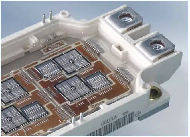
Typical high-power modules like IGBT packs employ a layered structure: die mounted on a DBC substrate, which is then soldered to a copper or AlSiC baseplate. The whole assembly is bolted to a cold plate. Each interface — solder joints, thermal interface materials (TIMs), and baseplates — adds thermal resistance, that impacts heat removal.
Key problems:
- Many thermal interfaces between the die and coolant.
- Material mismatches in coefficient of thermal expansion (CTE).
- Dependence on surface flatness, flow channel geometry, and coolant performance.
Improving thermal paths and minimizing resistances are critical for maintaining optimal junction temperatures, extending module lifespan, and supporting high-power-density applications.
Technical Approach or Experimental Procedure
Direct Mount on DBC Cold Plate
To address these challenges, the proposed solution involves embedding the DBC substrate into the cold plate. Copper and ceramic (Al₂O₃ or AlN) are joined using a high-temperature process, forming a robust monolithic structure. This integrated design maintains the electrical isolation provided by ceramics while embedding coolant channels directly under the heat source.
This integration:
- Eliminates the baseplate and its associated thermal resistance.
- Removes external TIMs (TIM2) between module and cold plate.
- Reduces total thermal resistance between the junction and the coolant.
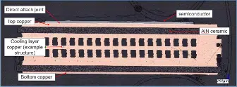
cold plate (coolant channels visible in this cross-section).
Materials used and their properties are listed in Table 1.
| Material Layer | Material | Bulk Thermal Conductivity (W/mK) | CTE (PPM/°C) |
|---|---|---|---|
| SiC Semiconductor | SiC | 375 | 4.0 |
| Joining Material | AuSn Solder | 50 | 15.9 |
| Ag sinter film | 200 | 18.92 | |
| Ceramic Isolation | Al2O3 | 35 | 6.5 |
| AlN | 170–200 | 4.2 – 5.7 | |
| Liquid Cold Plate | Cu | 360 | 16.7 |
Table 1: Bulk thermal conductivity, material layers, fully integrated power module/liquid cold plate.
Advantages include:
- High isothermal behavior due to monolithic copper structure.
- Flow channel resolution down to 0.3 mm, enabling high surface area contact.
- Flexible channel design to match coolant viscosity and required flow rates.
This level of integration allows for new cooling arrangements such as stacked modules or double-sided component mounting, enabling further increases in power density while minimizing volume and weight.
Enjoying this article?
Subscribe to Electronics Cooling for practical, engineer-focused insight on today’s thermal management challenges—plus immediate access to new digital magazine issues.
Subscribe here →
Results, Discussion, and Lifetime/Environmental Testing
Lifetime Testing with Water Coolant
To validate long-term reliability, DBC-based liquid cold plates were subjected to endurance testing using water as a coolant in a closed-loop system. A diode laser application was selected due to its high thermal load and continuous operation demands. Over 35,000 operational hours were recorded using unconditioned tap water, rather than deionized water or water with additives like antifreeze or biocides.
Cross-sectional analysis of the cooling channels showed minimal degradation—only ~50-70 μm of material erosion from the copper walls. Given the original channel width of 300 μm, this represents a tolerable expansion (~370 μm), with little functional impact on performance. See Graph 1 where length (channel width) is plotted over test time with the different shapes representing different flow conditions. At the 35kh mark, an increase in channel width can be observed. The widths less than nominal, e.g. for the 1.5 l/min flow, illustrate the effects of manufacturing tolerances. The grey bars indicate the manufacturing tolerance.
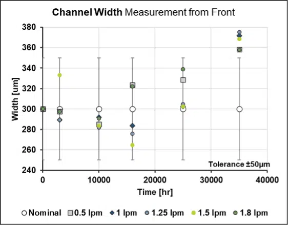
flow rates.
DBC liquid cold plates demonstrated exceptional corrosion resistance and structural integrity, even in sub-optimal coolant conditions like tap water or with antifreeze.
Environmental Thermal Stability
To assess the ability of the integrated assembly to survive harsh environments, thermal cycling tests were performed. Assemblies were exposed to temperature swings from room temperature down to -53°C and up to +140°C. We applied these conditions to a dry unpowered part. A 10 mm x 10 mm SiC IGBT die was sintered directly to the DBC substrate and tested for electrical performance before and after 2 cycles of extreme thermal fluctuation. Measurements focused on gate switching behavior and forward/reverse resistance under different modes.
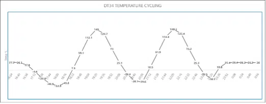
proposed assembly to show environmental stability.
| Test Type | ON – F | ON – R | OFF – F | OFF – R |
|---|---|---|---|---|
| Baseline Test | STATE | |||
| 102 | 77 | 236 | OL | |
| After Temperature Cycling | STATE | |||
| 104 | 185 | 243.5 | OL | |
| Delta (kΩ) | 2 | 108 | 7.5 | n/a |
Table 2: Switching behavior after thermal cycling (ON-F is forward resistance, ON-R is reverse resistance)
Findings:
- No cracking or delamination observed.
- Functional integrity retained post-cycle.
- More comprehensive testing (including leakage current and switching time) is planned.
Thermal Simulation of Cooling Performance
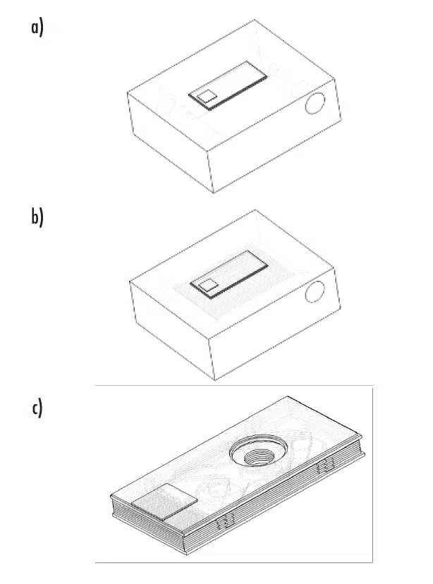
A three-way simulation was conducted to benchmark the new DBC-integrated cooler against conventional solutions:
- DBC with TIM on a simple single-channel cold plate.
- DBC with TIM on a complex, high-surface-area cold plate.
- Die directly mounted onto an integrated DBC cold plate.
Simulation parameters:
- Coolant: Water (70°C inlet temp)
- Heat Source: 5.45 mm x 5.45 mm SiC die dissipating 100 W
- Bonding: Silver sintering film (200 W/mK)
- TIM in scenarios 1 and 2: 100 μm, 1 W/mK
Figure 3 (a) has a single cylindrical channel in the cold plate for the coolant to pass through. This represents the technology used in many low-cost, readily available liquid cold plates. Figure 3 (b) shows a structure with 14 x 1mm x 1mm cooling channels with a pitch of 2mm, allowing for improved performance due to the significantly greater area (cooling liquid to solid interface). Also, the proximity to the heat source is improved. Figure 3 (c) shows a DBC integrated direct bond liquid cold plate with 300μm coolant channels.
The thermal interface material used for these simulations to connect the DBC to the coolers in Figures 3 (a) and (b) has a thickness of 100μm and bulk thermal conductivity of 1 W/mK, as modeled. Silver sintering film, with a bulk thermal conductivity of 200 W/ mK, was used as the joining material between the die and DBC for all three cases. Water with an inlet temperature of 70°C was used as the coolant.
Cold plates in configurations (a) and (b) and cooling layers in configuration (c) are made of copper with a bulk thermal conductivity of 401 W/mK and heat capacity at constant pressure of 384 J/kgK.
The heat source is a 5.45×5.45 SiC die with 100W of dissipated heat. AlN (170 W/mK bulk thermal conductivity) is used as the middle layers of DBC in these simulations.
Using computational fluid dynamics and thermal simulations in COMSOL, different flow rates of coolant (water) from 0.1 l/min to 1 l/min, with increments of 0.1 l/min, were simulated. The dissipated heat load (Ploss) in all cases was 100W. Figure 4 shows the temperature distribution on all configurations for a water flow rate of 0.1 l/min. A stark performance difference can be seen between configurations a) and b) versus c), all at the same Ploss.
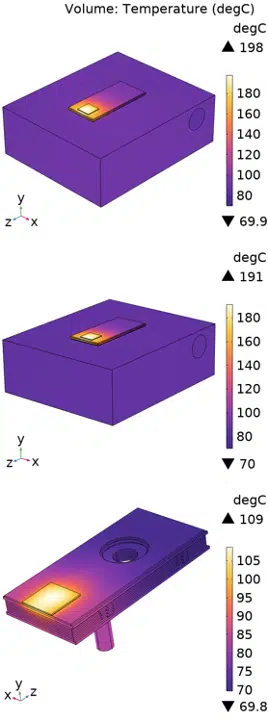
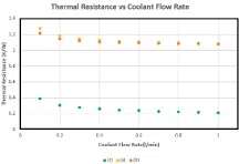
Graph 3 demonstrates the difference between the three configurations in thermal resistance versus water flow rate. This clearly demonstrates how much of a thermal barrier is created by thermal interface materials. Through the use of heat spreaders, these negative effects can be mitigated to a modest degree. However, heat spreaders add cost and require more space, which increases costs again. Figure 4 (a) shows the maximum temperature of 198°C when there is only one 4mm cooling channel vs. Figure 4 (b) where there are twelve 1mm channels with 2mm pitch, which bring the temperature down to 191°C. The substantial performance change is noticeable in Figure 4 (c) where the microchannel design brings the maximum temperature to 109°C.
| Die Size [mm] | Cooling Method | Flow per Liquid Cold Plate [l/min] | Thermal Resistance, Rth [K/W] |
|---|---|---|---|
| 5×5 | single | 0.4 | 0.42 |
| 5×5 | single | 2 | 0.33 |
| 5×5 | double | 0.5 | 0.15 |
| 5×5 | double | 2 | 0.06 |
| 10×10 | single | 1 | 0.15 |
Table 3: Rth, coolant flow speed and thermal resistance.
Results
- The DBC-integrated design significantly outperformed conventional methods.
- Absence of thermal interface layers greatly reduced junction- to-coolant thermal resistance.
- Lower housing temperature permits higher permissible power dissipation.
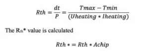
Experimental Validation of Rth (Thermal Resistance)
The measurement setup used 1 l/min flow and 40°C liquid temperature. Graph 4 shows the voltage, Uheating signal (in red using the left scale) at time zero. The heating of the device happened by applying 100A at the shown Uheating Voltage drop. The heating and the cool down are plotted into the same diagram but in temporal sequence. The Junction temperature (Tj, in blue, using the right scale) starts ~100ms after the heating is switched off to avoid the “ringing” seen in the early signal.
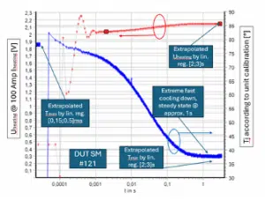
Uheating in red (left axis).
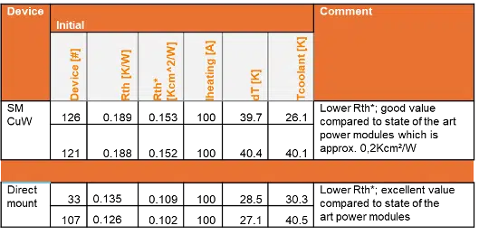
Table 3 shows results for 4 test samples. 2 of them (Direct mount) are as shown in Figure 2 while two (SM CuW) use a submount between the die and the cooler for potential stress relief.
The thermal impact of the submount is clearly visible with ~ 0.5 Kcm²/W in additional Rth. Between the 2 different samples, the maximum difference in resistance is ~ 15%. The same devices will be used for a lifetime test of 16 test articles including four replicates for four different configurations: 2 different packaging standards (SM CuW and Direct mount) and 2 test conditions (Tj ~100°C and Tj ~150°C). Also note that the measured Rth value (0.135 K/W) for direct mount of a 9x9mm die matched the simulation results in Table 3 last line (0.15 K/W) very well.
Traction Inverter Design with Direct Mount Technology
To compare the potential improvements possible with the suggested technology, the next step is to develop a new design and compare it to a more traditional approach.
Component Selection and Layout
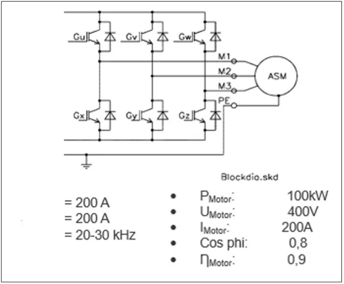
To demonstrate the applicability of the integrated DBC liquid cold plate design in a real-world scenario, a traction inverter layout is proposed. This design supports three-phase electric motors, such as asynchronous motors (ASM) or permanent magnet synchronous motors (PMSM), using standard IGBT (Insulated- Gate Bipolar Transistors) modules and freewheeling diodes. Each motor phase (U, V, W) requires two IGBTs and one diode per polarity (+ and –), resulting in a compact and efficient layout when deployed on DBC substrates. The inverter operates at 200 A and is scalable to customer requirements. Depending on the DC bus voltage (400–600 V), motor output power can range from 100 kW to 200 kW.
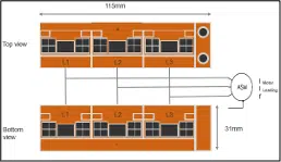
An important feature of the integrated DBC cold plate is its double- sided design. For symmetry and thermal stress balance during manufacturing, the structure has a front and back ceramic layer, both of which can be populated with components. This enables mechanical and electrical symmetry, simplifies signal routing, and facilitates module stacking.
Key advantages:
- Dual-sided population maximizes substrate usage.
- Simplifies phase and polarity separation.
- Facilitates parallel stacking for higher power density.
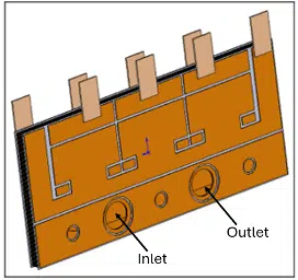
DBC Cooler Design The inner structure of the cooler can be designed to allow the liquid to enter from a common port. To allow a stacked arrangement, such as that displayed in Figure 7, a through hole can be manufactured to allow for a parallel fluid connection. From this common port, the liquid is guided directly under the heat source (IGBT die). With the appropriate cooling structure in place, this can look like what is shown in Figure 2. After heat exchange is accomplished, the fluid is collected and flows out of the common exit port.
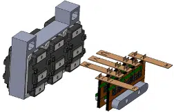
Summary
The proposed integrated DBC liquid cold plate design demonstrates a reduced junction temperature at the same operating point. Simultaneously, the assembly volume per watt dissipated is significantly reduced. In an approach with 6 high-power modules bolted to a very compact custom heat sink, a volume calculation yields approximately 214 mm3/W, compared to approximately 25.7 mm3/W for the proposed integrated DBC liquid cold plate. This represents a very significant and valuable reduction (~10x) in footprint and unit volume for a high-performance SiC IGBT module design.
It should be noted that fully integrated DBC all-copper liquid cold plates for extremely high-performance diode laser bar assemblies have been in volume production for more than fifteen years. This established production performance record indicates the success and long-term reliability achieved with this approach for a narrow application area and suggests that this process technology is suitable for use in other applications.
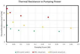
Another way to compare cooling performance is thermal resistance versus pumping power, as shown in Graph 7. Note that in this graph, the thermal resistance is normalized per area unit (mm²) of the heat source. This comparative performance of integrated module thermal resistance versus pumping power is significant for mobile electronic and electrical systems performance. The cold plate from Figure 3 (c) is simulated with water and Ampcool. The results are plotted with NREL data [4]. One example of this is in electrical drives designed for airborne applications, where thermal efficiency versus physical volume, weight, and system pumping power are critical to overall performance.
References
[1] Saeed, Rasha, “Design and characterization of high energy-density inductor,” PhD thesis, University of Nottingham, pages 48, 2018.
[2] Delphi Pedrosa et al. “Unified Power Converter Based on a Dual-Stator Permanent Magnet Synchronous Machine for Motor Drive and Battery Charging of Electric Vehicles, page 2, 2021.
[3] Geomety for Power Module used in this model was taken from the Wolfspeed website (XM3 Half-Bridge SiC Power Module Family | Wolfspeed). The custom cold plate is inspired by a Lucid inverter: (Inverter | Tech Talks | Lucid Motors (youtube.com)
[4] Sreekant Narumanchi, Data points in Graph 7 (NREL) taken from NREL ThermalTechnologiesSummary_2023 presentation.

