Introduction
The evolution of modern automotive engineering is defined by a single, escalating conflict: the demand for massive computing power versus the shrinking physical space available to house it. As vehicles transition from mechanical machines to “computers on wheels,” the thermal management of Advanced Driver Assistance Systems (ADAS) has moved from a secondary concern to a critical path for reliability.

For decades, automotive electronics were relatively simple. An Electronic Control Unit (ECU) would dissipate a few watts of heat, housed in a metal box with ample airflow around it. Today, however, the landscape has shifted. We are now embedding super-computer-class processors, high-frequency radar modules, and high-fidelity optical sensors into the tightest & most hostile locations in the vehicle.
The challenge is not that the fundamental laws of thermodynamics have changed, but that the environment in which they operate has become far more restrictive. ADAS modules must endure ambient temperatures ranging from -40°C to 105°C, intense solar loading, and isolation from fresh airflow.
For a thermal engineer, the old playbook of “adding a fan” or “sizing the heatsink” is obsolete. Success now requires a deep understanding of the physics of heat transfer in stagnant, confined fluids.
The “Sealed Box” Constraint
One of the primary drivers of this thermal complexity is the requirement for rugged environmental protection. Unlike a server in a data center, some ADAS hardware is located on the exterior of the vehicle, exposed to the elements. To survive road salt, mud, rain, and high-pressure car washes, these sensors must meet rigorous Ingress Protection (IP) standards.
- Surround View Cameras: Often mounted in side mirrors or the front grille, these must meet IP67 or higher, which guarantees protection against high-pressure (100 bar), high-temperature (80°C) water jets.
- Radar Sensors: Tucked behind bumpers or integrated into fascia, these units require similar sealing to prevent moisture intrusion, which would attenuate their RF signals.
From a thermal perspective, achieving IP67 creates a “closed system.” The unit must be sealed with gaskets and is sometimes potted with potting compound. This eliminates mass transfer — meaning no cool air can enter the enclosure, and no hot air can leave. The air trapped inside becomes a fixed volume of “dead air.” Consequently, the housing itself must serve as the only heat exchanger, rejecting 100% of the internal thermal load to the outside world.
Defining “Confined Spaces” in Electronics Cooling
What exactly makes a space “confined”? In thermal engineering, it is not simply about small physical dimensions, it is about how air behaves within those dimensions. A confined space represents a specific physical regime in which the enclosure geometry suppresses natural air movement. When the distance between a heat source, such as a printed circuit board (PCB) and the heat sink (enclosure wall) becomes small, airflow is restricted and begins to behave differently.
As the gap narrows, thermal boundary layers from opposing surfaces begin to interact and interfere with one another. Instead of forming stable convective plumes, the air becomes slow-moving and even locally stagnant sometimes. In this regime, convection loses effectiveness, and heat transfer shifts toward conduction through solid materials and stagnant air layers.
Under these conditions, radiation can also become relevant. In tightly spaced locations, surfaces are exposed to each other more directly and with limited airflow to carry heat away, radiative exchange between the PCB and enclosure walls can contribute a significant portion of total heat transfer — especially as temperatures rise. While radiation rarely dominates, its relative contribution increases as convection is suppressed.
The Physics of Stagnation
The Rayleigh Number (Ra) characterizes whether heat moves through a gap via convection or conduction. It represents the balance between flow driving forces (buoyancy) and resistive forces (viscosity). When the gap is tiny, viscous forces dominate, thereby preventing air movement.
Formula:
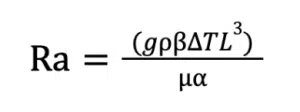
Where:
g: Acceleration due to gravity
L: Characteristic Length
β: Thermal expansion coefficient
µ: Viscosity
∆T: The temperature difference
α: Thermal diffusivity
The most critical variable in this equation is the gap size, L, because it is cubed. This means that if you reduce an air gap from 10mm to 2mm (a factor of 5 reduction), the driving force for natural convection drops by a factor of 125 (53).
In many ADAS designs, L is so small that the resulting Rayleigh Number falls below the Critical Rayleigh Number (approximately 1708[1] for horizontal layers). Below this threshold, buoyancy is simply too weak to overcome the viscosity of the air. The air remains stationary, and heat transfer shifts entirely from convection to conduction. This is why adding “more fins” to a tightly packed camera unit is often ineffective. Physics of the gap size simply won’t allow the air to move.
Heat Transfer Modes in Confined Enclosures
Conduction:
In confined ADAS electronics, conduction is often the dominant heat transfer mechanism. Heat generated at semiconductor junctions must travel through multiple layers: die attach → package → PCB → thermal interface materials → housing → vehicle environment. Because the air gap is an insulator, any inefficiency in the conductive path directly translates to higher component temperatures.
One common mistake is overestimating conduction effectiveness in early simulations. Many engineers rely on idealized contact assumptions or datasheet material conductivity, but in confined spaces these deviations are amplified because alternative cooling paths are limited.
Natural Convection:
As established by the Rayleigh Number, natural convection is often negligible in these systems. However, it is not always zero. In slightly larger modules, such as ECUs located under the dashboard, there may be enough internal volume to allow weak circulation to occur.
Narrow gaps around these electronic modules limit plume formation and opposing boundary layers interfere with each other before significant velocity can develop. As a result, air movement may be localized and weak, contributing only marginally to heat removal. Orientation effects – vertical versus horizontal mounting – can still influence temperature distribution, but the overall heat transfer coefficient remains low (on the order of <1W/m2K).
Radiation:
Radiative heat transfer is usually neglected in electronics cooling discussions, yet in confined & low-flow environments it can contribute significantly in heat dissipation.
Inside compact enclosures, view factors between PCBs and enclosures are often high. A raw, shiny aluminum housing has an emissivity of roughly 0.05-0.2. It acts like a mirror, reflecting heat back at the PCB. By simply anodizing that aluminum black or coating it, the emissivity jumps to 0.80 or higher. Heat transfer via radiation depends on the absolute temperature to the fourth power (T4) and the emissivity (ε) of the surfaces. Hence, an anodized enclosure is able to dissipate the heat more effectively than an unanodized surface.
While radiation alone rarely solves thermal challenges, it can provide incremental margin when other mechanisms are saturated. In tightly packaged ADAS systems, such incremental gains can be valuable.
Why Intuition Fails: Thermal Chamber Testing vs. Reality
One of the key differences between confined and open electronics cooling is that airflow rarely becomes fully developed. In many ADAS enclosures, the available flow length is about the same as the thermal entry length, meaning that the boundary layers are always forming but do not have enough distance to settle into a stable pattern.
As a result:
- Flow tends to remain laminar, even with large temperature differences
- Stagnant regions form easily and can persist inside the enclosure
- Local heat transfer coefficients become highly non-uniform across surfaces
Engineers familiar with larger, better-ventilated enclosures may expect convection to strengthen simply because the temperature rise is higher. In confined spaces, however, higher temperatures do not necessarily produce stronger airflow. Instead, they often indicate that tight spaces restricts airflow, and the system becomes effectively more conduction dominated.
This strong dependence on scale and geometry is one reason thermal performance seen in benchtop prototypes or open-air setups may not carry over to the final production installation. Therefore, it is essential to develop a representative test setup that not only allows elevated-temperature testing in a thermal chamber but also enables controlled airflow around the module to better replicate the effective heat transfer conditions of the final installation.
Environmental Boundary Conditions
In confined electronics cooling, boundary conditions often dominate the thermal design strategy. For instance: for an ADAS camera module mounted behind the windshield near the rear-view mirror, external ambient temperature, solar loading and internal boundary conditions all influence temperature rise and effectively impacting the available thermal headroom for the electronics to reject heat.
Solar Loading:
A forward-facing camera mounted against the windshield is effectively in a greenhouse. Solar radiation of around 1,000 Watts/meter² is incident onto the housing of the camera. The metal enclosure, which is supposed to be heatsink, can become very hot. The ambient temperature of the housing can rise to 90°C solely from the sun, leaving almost no thermal margin for the electronics to operate.
Tight Packaging Spaces:
Camera modules are often installed in tight spaces surrounded by trim parts, brackets and cosmetic covers. These components may restrict airflow and reduce the convective heat transfer coefficient, but the airflow is never truly zero. The module typically experiences weak convection, influenced by factors such as cabin ventilation operation, vehicle speed and leakage paths around trim features. This “low-but-not-zero” airflow can make performance highly sensitive to geometry, orientation and small gaps. These conditions are difficult to generalize with a single convection coefficient number during a simulation model setup.
Internal Boundary Conditions:
Internally, assumptions about power dissipation and heat spreading are equally important. ADAS camera modules are not “single heat source” devices. They typically contain multiple heat-generating components such as:
- Image sensors
- Serializers / de-serializers
- Power management ICs
- Processors & microcontrollers
- Memory devices
These components often have different duty cycles, different peak power behavior and different locations on the PCB. A uniform power dissipation assumption may produce a reasonable average temperature prediction, and it can mask localized hot spots that drive reliability risk.
Ultimately, design success depends on applying real-world physics to define boundary conditions and identifying the thermal strategy best suited for this environment.
First Principles
To better match physical conditions and account for the limitations of heat transfer in confined spaces, engineers should adopt the following first-principles approach for next-generation ADAS systems.
| Strategy | Action | Physics |
|---|---|---|
| Lower thermal resistance (Rth) in the main heat transfer path | Create a direct conduction path from ICs → PCB → interface material → enclosure | Conduction dominates in confined spaces. Reducing Rth has the biggest impact on peak temperatures. |
| Maximize heat spreading before rejection | Add heat spreaders and interface materials | Spreading reduces local hot spots by increasing effective areas for dissipation |
| Use radiation as a supporting mechanism | Increase emissivity & absorptivity of enclosure components by anodization | Radiation can help significantly with heat transfer, especially in low air flow spaces |
| Component placement | Place high density ICs near the best conduction path, not in corners or isolated PCB region | Good placement and board design help with efficient heat spreading. Poor placement increases hot spots. |
| Use real boundary conditions | Include vehicle-like setup with solar loading, limited airflow, cosmetic covers that affect airflow | Using correct boundary conditions helps decide the best thermal strategy for heat dissipation |
| Prioritize early thermal architecture decisions | Validate heat transfer path, materials and interfaces early in the design through simulation & optimization | Late thermal fixes have limited flexibility and effectiveness in confined systems |
Conclusion
Cooling electronics in confined spaces is not simply a scaled-down version of conventional thermal design. In ADAS camera and sensing modules, limited airflow, tight packaging, and strong dependence on boundary conditions shift the problem toward conduction-dominated heat removal, with supporting contributions from natural convection and radiation. As computing power and functional density continue to increase, thermal success will depend less on adding complexity and more on applying first-principles thinking early by establishing robust heat paths, minimizing interface resistance, and accounting for real vehicle conditions, such as solar loading and tight packaging spaces. With a physics-based approach supported by correlation testing, engineers can build next-generation ADAS hardware that meets performance targets while maintaining long-term reliability.
References
[1] Incropera, F.P., DeWitt, D.P., Bergman, T.L., and Lavine, A.S., Fundamentals of Heat aGodnd Mass Transfer, 7th ed., Wiley, 2011.