Power electronics in modern computing, energy conversion, and industrial systems increasingly operate under pulsed or highly variable loads. Voltage regulators and power conversion units inside server racks experience rapid transients as workloads shift. EV drivetrain inverters see intense current pulses during acceleration and braking. Industrial motor drives and power converters cycle through high-power events repeatedly over their service life.
In each case, peak heat generation during a pulse can far exceed what steady-state cooling can absorb in real time. Oversizing the cooling system to handle peak load adds cost, weight, and energy consumption; with much of that capacity sitting idle between pulses. A more efficient approach is to store the burst energy locally during the pulse and release it gradually to the cooling system afterward, sizing the base infrastructure for the average, rather than peak, load.
Phase change material (PCM)-based latent thermal energy storage (TES) systems do exactly this. By absorbing heat isothermally through PCM melting during a power pulse, they buffer peak thermal loads and protect electronics from temperature spikes without requiring larger steady-state cooling capacity. This article presents a novel additively manufactured metal-polymer composite TES system for this purpose, along with a validated computational design tool.
Why Latent Storage for Pulsed Loads
Because PCMs store 5 to 14 times more thermal energy per unit volume than sensible storage materials at comparable temperature differences [3], they can absorb a given energy pulse in a significantly smaller package. For example, paraffin wax stores roughly 200 kJ/kg via latent heat compared to water’s sensible capacity of about 4.2 kJ/kg·K. More importantly for power electronics, PCM melting is isothermal, which can allow component temperature to stay nearly constant during a pulse. This directly reduces the junction temperature swings that drive thermal fatigue in IGBTs, MOSFETs, and diodes, thereby extending device lifetime compared to sensible or purely convective approaches.
The Novel Cross-Media TES System
The TES system is based on a patented cross-media metal-polymer composite heat exchanger (HX) developed at the AHX-PI Laboratory, University of Maryland [1]. It takes advantage of polymer’s low cost, light weight, and corrosion resistance, while the cross-media approach leverages metal’s high thermal conductivity independent of the polymer’s own low conductivity, resulting in heat exchangers with higher thermal conductivity than conventional polymer heat exchangers. It consists of alternating fluid and PCM-filled polymer channels, with continuous high-conductivity metal wires in a staggered tube-bank geometry spanning both channel types, as shown in Figure 1.
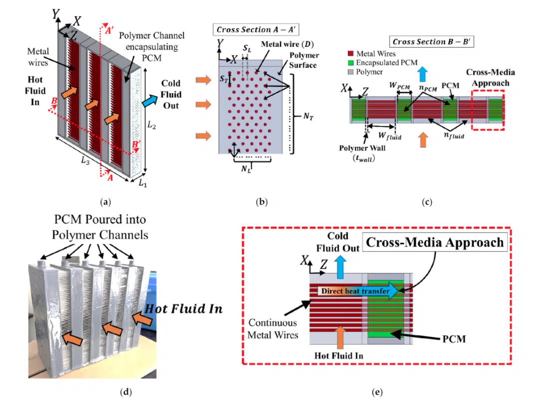
The metal wires are the key innovation. In conventional polymer HXs, heat must conduct through the polymer itself, which has inherently poor thermal conductivity in the range of 0.2 to 0.5 W/m·K. The cross-media wires bypass the polymer entirely to provide a direct axial conduction path from the fluid to the PCM and raise the effective thermal conductivity by more than an order of magnitude. The PCM is held directly within the polymer channels without micro-encapsulation, eliminating the process that accounts for up to 99% of conventional PCM system cost [2]. The entire system is 3D printed using a customized dual-head printer with separate polymer and metal heads, enabling the complex cross-media geometry while supporting rapid, low-cost design iteration.
A Computationally Efficient Design Tool
Designing a TES requires optimizing the thermal performance that is influenced by factors such as wire diameter and spacing, PCM channel width, flow rate, and material selection. The key performance question, how quickly the PCM melts under a given pulsed load, involves a transient phase-change problem that conventional CFD tools can solve accurately, but slowly. A single simulation can take hours; sweeping a realistic design space is not feasible on an engineering schedule.
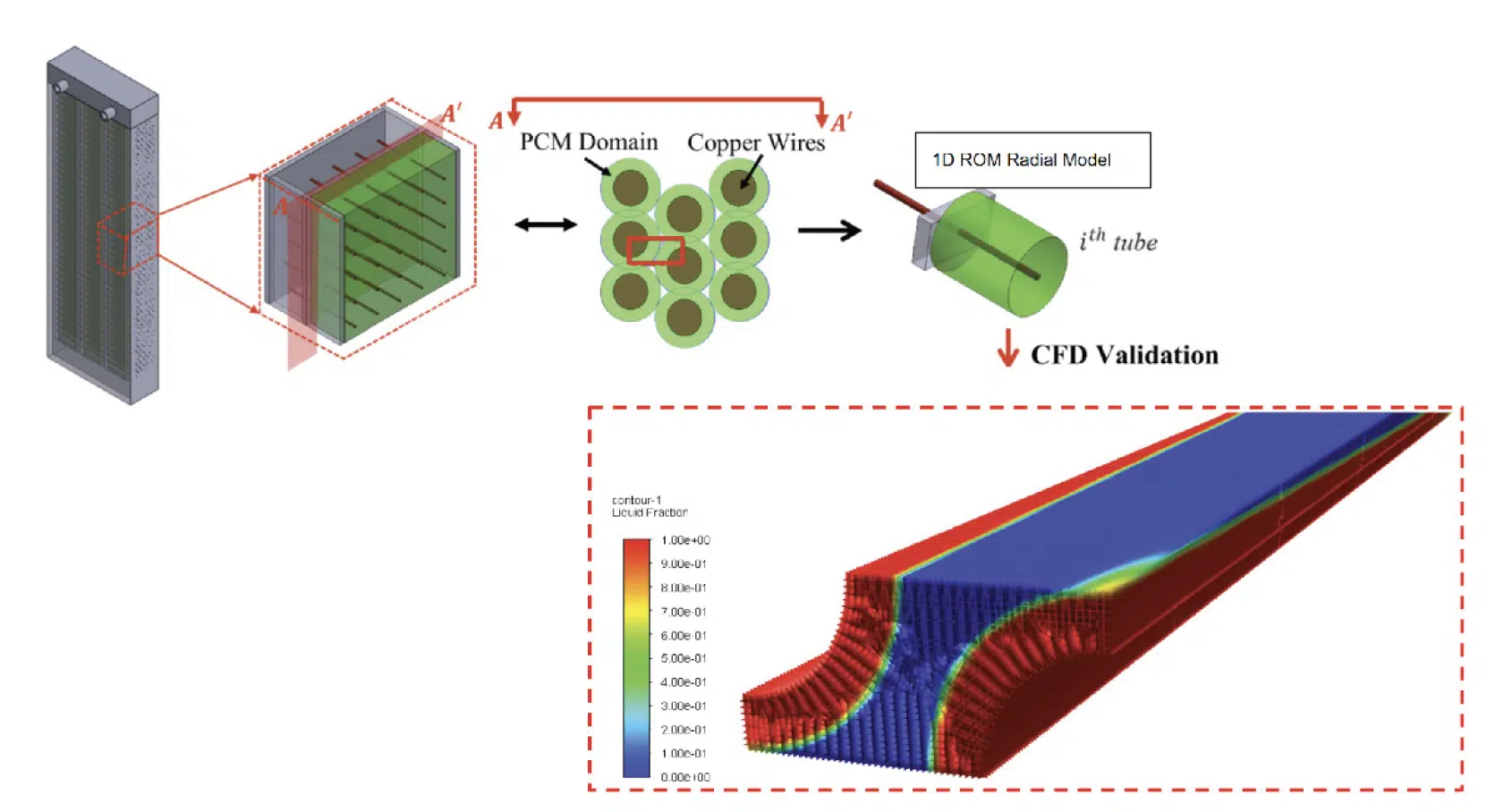
The 1D reduced-order model (ROM) developed for this system [4] predicts TES performance in seconds by reducing the full HX domain to a single representative PCM-wire element, as shown in Figure 1 (e) and solving it analytically. At each time step, the ROM computes total thermal resistance (Rtotal) (fluid-side convective: Rfluid, wire axial conductive: Rcond, and transient PCM cylindrical: RPCM) and advances the melt front.
Rtotal (t) = Rfluid + Rcond + RPCM (t)
This runs across all wire rows, capturing the fluid temperature drop along the flow direction. An assumption of 1D radial conduction in the PCM is made, using geometrical tube bank spacings to obtain equivalent melt radius. This assumption holds for Ste, Stefan numbers (ratio of sensible heat to latent heat) below 0.1, a condition satisfied by the low-melting-temperature PCMs (20-25C) relevant to electronics cooling.
Based on the above thermal resistance equation, the ROM’s governing equations are derived using heat transfer rate, expressed as the ratio of temperature-difference between fluid-inlet and PCM to Rtotal, and are non-dimensionalized to predict melt-radius as a function of time [4]. These governing equations are shown below, which use non-dimensionalized time, t* and non-dimensionalized radius, r*:
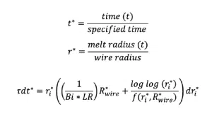
Where:
- τ (dimensionless time constant) refers to Ste * Fo, Fo refers to Fourier number and captures approach temperature and PCM properties, higher τ means faster melting.
- Bi·LR (resistance ratio) where Bi refers to equivalent Biot number and LR to equivalent length ratio of WPCM to melt radius at t=0s, captures the fluid-to-wire resistance balance. Higher Bi * LR, achievable through increased flow rate or smaller wire diameter, means faster heat delivery to the PCM.
- R*wire (wire resistance parameter) which is the ratio of axial resistance of wire embedded in PCM to maximum radial resistance of PCM. Low R*wire, achieved with high-conductivity additively manufacturable metals such as copper and aluminum, with minimum wire diameters around 0.4 mm limited by nozzle size in processes such as FDM during additive manufacturing and maintains uniform temperature distribution radially along the wire length and keeps the 1D assumption valid.
Validation
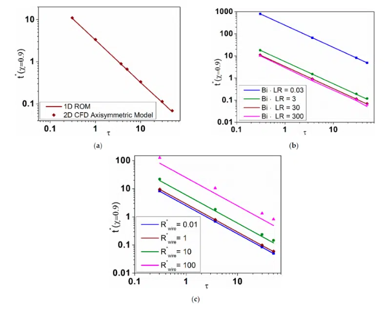
The ROM was validated numerically against a 2D CFD axisymmetric reference model across a broad parametric sweep [4], as shown in Figure 2.
For the ranges most applicable to power electronics cooling (τ from 0.3 to 50, Bi·LR from 3 to 30, R*wire ≤ 1) agreement is within 3 to 7%, as shown in Figure 3. Deviations greater than 10% occur only at extremes (Bi*LR ≥ 300 or R*wire ≥ 10), in which axial PCM conduction dominates. This condition is undesirable as it violates the 1D radial heat transfer assumption of the model and is straightforward to avoid.
Experimental validation on a fabricated 3D-printed prototype that used n-hexadecane as the PCM confirmed the ROM predictions of complete melting time within 17% and freezing time within 8% of measured values [5]. This level of accuracy is well suited to early-stage design optimization in which the speed advantage of the ROM over full CFD is most valuable.
Design Guidance
The ROM was successfully used to optimize a 19.2 kJ cross-media TES unit for a pulsed-power application with peak discharge power of about 3.2kW and average discharge power of about 360W [5]. Table 1 summarizes the recommended parameter ranges for power electronics cooling. Designs should target Bi · LR between 3 and 300 with Rwire ≤ 1 to maximize energy absorption rate. Wire pitch ratio (ST /SL) should be near 1.27 or 3.5 to minimize PCM overlap effects and keep ROM error below 10%. PCM melting point should be 30 to 50°C below the device junction temperature limit to provide adequate thermal buffering while ensuring re-solidification between pulses.
| Parameter | Target Range | How to Achieve it |
|---|---|---|
| τ | Application-set | Set by pulse thermal load and PCM melting temperature selection |
| Bi · LR | 3 to 300 | Increase fluid flow rate or reduce wire diameter |
| R☆wire | ≤ 1 | High-conductivity wire (e.g., copper); shorten PCM channel width |
| ST/SL | 1.27 or 3.5 | Minimizes PCM overlap effects; keeps ROM prediction error below 10% |
Table 1: Recommended design parameter ranges for pulsed-power electronics cooling
Application Examples
Data center power electronics: Voltage regulators inside server racks experience repeated thermal transients as processor loads shift. A compact cross-media TES system on the power module cooling path buffers these transients isothermally, reducing peak junction temperatures and extending device lifetime without changes to facility-level cooling.
Electric vehicle power electronics: EV inverters and on-board chargers experience intense current pulses during acceleration, braking, and fast charging. The isothermal absorption of the cross-media TES directly reduces junction temperature swings, which are the primary driver of thermal fatigue, in a lightweight, low-cost package suited to automotive packaging constraints.
Industrial systems: Motor drives, welding supplies, and high-power test equipment generate repetitive burst loads. The ROM enables fast sizing for specific pulse energy and duty cycle requirements, and the low fabrication cost of the 3D-printed system makes custom thermal solutions practical for lower-volume industrial applications such as for a 400A welding power supply with 6s welding pulse.
Conclusions
A novel additively manufactured metal-polymer composite TES system for pulsed-power electronics cooling has been presented alongside a validated 1D ROM design tool. The system eliminates expensive PCM encapsulation through macro-containment and delivers high effective thermal conductivity through the cross-media wire architecture. The ROM, validated within 10% of 2D CFD and 17% of experimental measurements, enables systematic design space exploration in seconds, making PCM-based latent storage practical for power electronics engineers working on data center, EV, and industrial cooling challenges.
References
[1] Kailkhura, G.; Mandel, R.K.; Shooshtari, A.; Ohadi, M. Numerical and Experimental Study of a Novel Additively Manufactured Metal-Polymer Composite Heat-Exchanger for Liquid Cooling Electronics. Energies 2022, 15, 598.
[2] Höhlein, S.; König-Haagen, A.; Brüggemann, D. Macro-Encapsulation of Inorganic Phase-Change Materials (PCM) in Metal Capsules. Materials 2018, 11, 1752.
[3] Mehling, H.; Cabeza, L.F. Heat and Cold Storage with PCM. Springer: Berlin, 2008.
[4] Kailkhura, G.; Mandel, R.K.; Shooshtari, A.; Ohadi, M. A 1D Reduced-Order Model (ROM) for a Novel Latent Thermal Energy Storage System. Energies 2022, 15, 5124.
[5] Kailkhura, G. Numerical Modeling and Experimental Study of a Novel Metal-Polymer Composite Heat Exchanger for Sensible and Latent Thermal Energy Storage Applications. PhD Dissertation, University of Maryland, College Park, 2022.