
High-density AI racks no longer fail one signal at a time. Workload, flow, pressure, coolant chemistry, and facility heat rejection now move together. Thermal engineers need an orchestration layer that connects those signals to the heat-transfer and hydraulic models behind the cooling design.
The Failure Pattern
A modern AI rack does not fail like a light switch. It starts as a disagreement between systems.
Graphics processing unit (GPU) telemetry says that the job is still running. Supply temperature remains inside its limit. The coolant distribution unit (CDU) keeps compensating, and the building management system (BMS) sees nothing urgent. Meanwhile, branch flow is drifting; the pressure drop across the branch, commonly tracked as differential pressure or Delta-P, is rising; the GPU-to-coolant approach temperature, which is the difference between GPU temperature and the coolant entering the cold plate, is increasing at stable GPU power; and the coolant’s electrical conductivity is moving above its commissioned baseline.
Nothing has failed, but the system is already spending thermal margin. That is the problem with managing liquid cooling as separate mechanical, chemical, and controls data streams. Each signal can look manageable in isolation, while the combined trend shows whether expensive compute can remain online. This is why AI factories need thermal orchestration.
Practical Takeaway
Liquid cooling is no longer a background utility in GPU-dense AI infrastructure. It is part of the compute reliability envelope.
Thermal orchestration connects five aspects of liquid cooling that are often monitored separately: GPU behavior, cold-plate performance, hydraulic stability, coolant health, and bounded control actions. For the thermal engineer, that expands the deliverable beyond cold-plate capacity and pressure drop. The design must expose measurable state, valid operating bounds, and models that controls and operations teams can use. The goal is to maintain stable and useful compute even as workload, flow, chemistry, and facility conditions change.
The Problem: Cooling Data Is Still Fragmented
Most liquid-cooled AI infrastructure is monitored as a collection of separate systems. GPU telemetry lives in one world, CDU data lives in another, and facility-water conditions are tracked somewhere else. Lab reports describing coolant chemistry may not reach the operations team until days or weeks after sampling.
The result is not a lack of data but a lack of context. A 2°C increase in GPU-to-coolant approach temperature may be harmless after a workload change. The same drift at stable GPU power, rising Delta-P, and coolant conductivity moving away from baseline is an early reliability signal. Thermal orchestration is the discipline of reading those signals together.
AI Factories Make Cooling a Compute Problem
A conventional enterprise rack can often be treated as a set of independent servers. A modern AI rack behaves more like a tightly coupled production cell. GPUs, central processing units (CPUs), high-speed interconnects, power delivery, and software scheduling interact across the rack. When one thermal zone loses margin, the effect can show up as lower boost behavior, workload imbalance, higher pumping power, or a narrower operating envelope: a smaller range of load, supply temperature, and flow in which the rack can operate without implementing throttling or protective action.
NVIDIA’s GB200 NVL72 connects 36 Grace CPUs and 72 Blackwell GPUs in a rack-scale, liquid-cooled NVLink domain [1]. That architecture changes the meaning of cooling stability. A cold plate, manifold, CDU, and facility-water connection are part of the performance path for expensive accelerated compute.
The case for liquid cooling is clear. Benchmarking work on accelerated GPU systems reported liquid-cooled platforms operating at lower and more stable GPU temperatures than comparable air-cooled platforms under load, with a reported performance and efficiency benefit [2]. Direct-to-chip research is also becoming more package-aware, with design work targeting the non-uniform heat maps of modern accelerators [3]. The next step is to operate the loop with the same systems mindset used for compute and networking.
Thermal Orchestration Is the Missing Control Layer
Cooling answers a narrow question: can the system remove the heat necessary to maintain suitable temperatures? Thermal orchestration asks a broader question: can the system maintain suitable temperatures as workload, hydraulics, coolant condition, and facility conditions change?
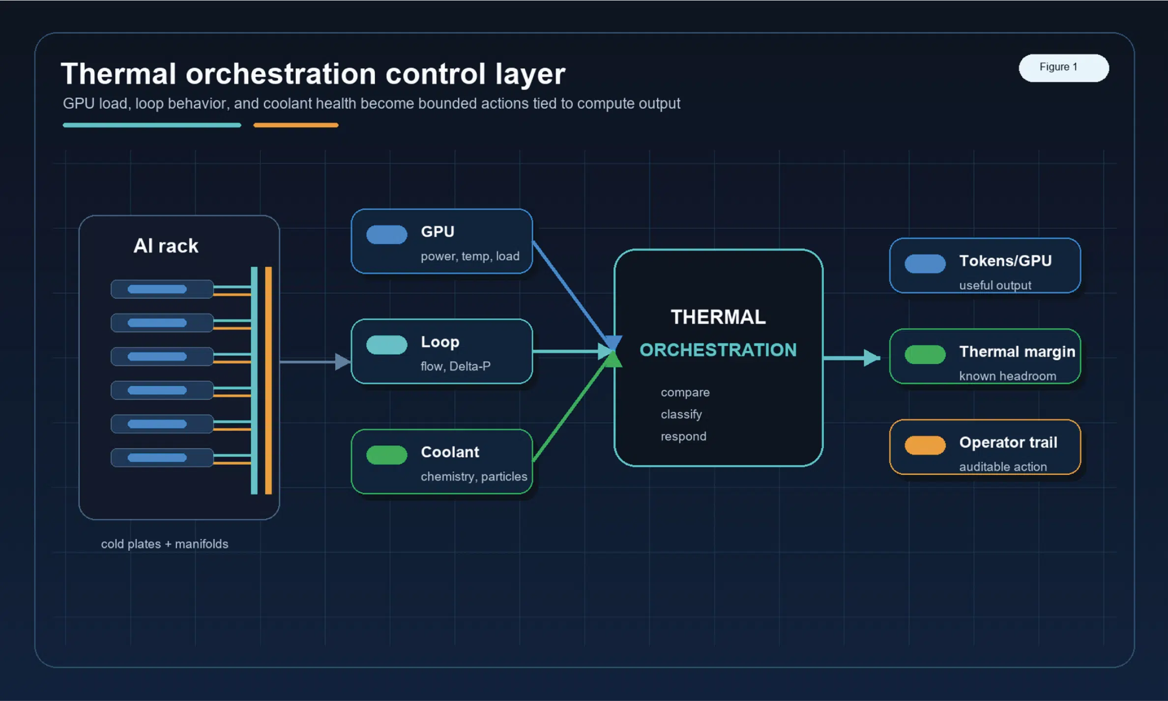
A thermally orchestrated architecture has three layers:
- Physical heat removal: cold plates, quick disconnects, manifolds, pumps, valves, heat exchangers, and facility water.
- Condition awareness: temperature, flow, pressure, coolant chemistry, particles, inhibitor reserve, dissolved oxygen, and leak-related signals.
- Decision logic: defined rules for when to hold, rebalance, protect, schedule maintenance, or escalate to an operator.
Figure 1 shows this stack as one control layer, not a pile of disconnected dashboards. The loop does not just remove heat. It reads its own state and chooses the next safe response.
The Four Languages of a Cooling Loop
A thermally orchestrated loop speaks four languages at once. The GPU language tells what the compute is asking for: power, utilization, temperature, throttling state, and workload class. The thermal language tells whether heat is leaving the silicon efficiently: supply temperature, return temperature, approach temperature, CDU performance, and facility-water conditions.
The hydraulic language tells whether the loop is still moving fluid cleanly: flow, differential pressure, pump command, valve position, and filter differential pressure. The fluid-health language tells whether the working medium is still safe: pH, conductivity, dissolved oxygen, inhibitor reserve, particles, metals, and microbial indicators where appropriate.
Think of the loop like an orchestra. GPU telemetry carries the melody, flow and pressure keep the rhythm, coolant chemistry sets the tuning, and the orchestration layer tells the operator whether the score is healthy or drifting. Figure 2 summarizes those four languages as one operating picture.

What Thermal Orchestration Sees That Single Alarms Miss
Consider a rack running a stable training workload. GPU power is steady, supply temperature remains within limits, and no thermal alarm fires. Over 72 hours, the GPU-to-coolant approach temperature rises by 1.5°C, branch flow falls slightly, filter Delta-P creeps upward, pump command increases to maintain target flow, and coolant conductivity begins to move above baseline.
Any one of those signals might be explainable. Together, they tell a different story: the loop is compensating for a developing restriction while the coolant condition is moving away from baseline. That is not an emergency yet. It is a maintenance window waiting to be scheduled.
Why Coolant Health Belongs in the Loop
Many data center monitoring systems collect temperature, flow, and pressure, but those signals do not fully describe the loop condition. Coolant can remain at the commanded flow while its electrical conductivity rises, inhibitor reserve falls, dissolved oxygen increases, or particles and wear metals accumulate. Because those changes may develop between sampling events, a periodic lab result may not show when the drift began or how quickly it is progressing.
Industry guidance on water-cooled servers treats water quality, wetted materials, filtration, and operational process as design concerns [4]. That point is important for AI factories. The coolant is not passive. It is a working medium that touches the same surfaces relied on for thermal performance, sealing integrity, and long operating life.
Recent industry writing has described predictive coolant health as a missing reliability layer in AI data centers [6]. Others discuss coolant-health drift and wet-surface thermal margin in more detail [7, 8]. The practical takeaway is simple: coolant health should be interpreted along with thermal and hydraulic data, not reviewed as a separate maintenance paperwork item.
Self-Healing Does Not Mean Unsupervised Control
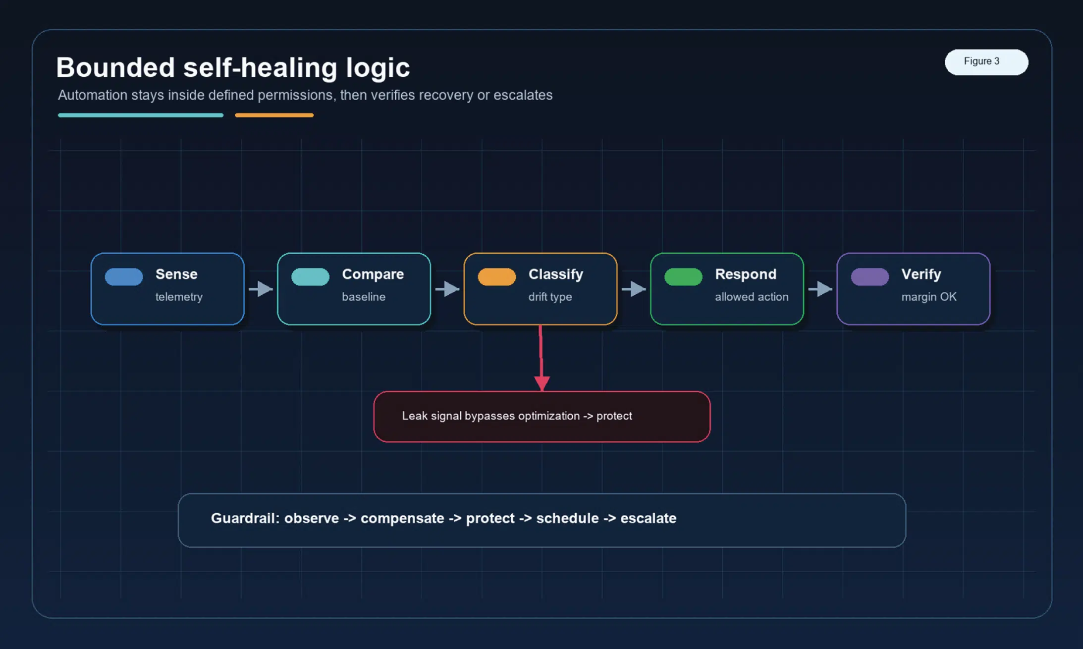
In AI infrastructure, self-healing should not mean giving a black box unrestricted authority to change pump speed, valve position, or temperature targets. A realistic self-healing cooling loop follows a staged pattern: sense, compare, classify, respond, verify, and escalate. Figure 3 shows that pattern as a bounded feedback loop, not an unrestricted automation claim.
Safety comes from bounded responses tied to specific evidence. If a branch warms at a stable load, the logic compares the observation with its baseline and checks pump command, flow balance, and filter Delta-P. If coolant chemistry moves outside a defined band, the system can hold a more conservative operating target, increase sampling frequency, or limit an operating mode that would consume margin.
If the response does not recover margin, it escalates with a clear record of what changed, what action was taken, and what happened next.
The Bounded Action Ladder
The safest automation pattern is not ‘AI controls everything.’ The safest pattern is a bounded action ladder: observe, compare, compensate, protect, schedule, escalate.
Each rung has permission limits, each action has a reason, and each response leaves an audit trail. Table 1 shows illustrative thresholds, not universal setpoints. Exact values should be tuned to the coolant, hardware, commissioning baseline, measurement uncertainty, and operator risk model.
This keeps the system explainable. In high-density GPU environments, an automatic response is useful only if an operator can understand why it happened, what limit it respected, and whether it recovered margin.
| Observed Condition |
First Response | Escalation Path |
|---|---|---|
| Mild thermal drift: 1 to 2°C rise in approach temperature at stable GPU load | Compare against baseline; check pump command, branch flow, and filter Delta-P | Inspect branch or cold plate if drift persists beyond the agreed window |
| Thermal drift plus chemistry movement: conductivity above baseline with a rise in approach temperature | Increase sampling frequency; review inhibitor reserve, oxygen, and particle trend | Plan coolant or filtration service before margin is consumed |
| Hydraulic restriction: 10 to 15 percent Delta-P shift with stable chemistry | Inspect valve state, pump RPM, air, quick disconnects, and filter loading | Isolate or service affected branch |
| Leak-related signal | Bypass optimization logic and move directly to protection | Isolate, inspect, and document root cause |
Table 1: Bounded response ladder with illustrative operator thresholds.
No Baseline, No Orchestration
Thermal orchestration does not start when something drifts. It starts at commissioning. Acceptance testing should capture representative workload conditions, GPU power, cold plate approach temperature, branch flows, pressure drops, pump speed, valve positions, filter state, facility-water conditions, and coolant chemistry.
Without a clean baseline, the system cannot tell the difference between normal workload variation and real degradation. A meaningful comparison needs the same rack, similar GPU load, similar supply temperature, similar valve state, similar flow condition, and known coolant chemistry. Closed-loop data methods are a useful direction here because they infer changing thermal performance from real operating measurements [5].
Why This Is a Compute Availability Problem
Thermal orchestration is not only a cooling improvement. It is a compute availability strategy.
When cooling margin erodes, the business does not experience ‘slightly worse heat transfer.’ It experiences lower boost behavior, fewer tokens generated per GPU, tighter workload scheduling, higher pump energy, more conservative operating envelopes, unplanned maintenance, and reduced confidence in high-value GPU capacity.
In an AI factory, useful outputs include tokens, training progress, simulation throughput, and inference capacity. Cooling health belongs in that production model.
What This Changes for Thermal Engineers
Start with the design review. In addition to cold-plate capacity, a liquid-cooling review for GPU infrastructure should cover sensor placement, sample points, filtration strategy, materials compatibility, data retention, control authority, and the response expected when a limit is crossed.
The orchestration layer also needs a compact set of physics-based models from the thermal design team:
- Coolant heat balance: heat removed equals mass flow multiplied by specific heat and coolant temperature rise, checked against IT power and expected heat capture.
- Component-to-coolant resistance: the expected relationships among GPU power, coolant inlet temperature, flow, and GPU-to-coolant approach temperature.
- Hydraulic response models should include branch pressure-flow curves, filter pressure drop, pump operating points, and valve authority across the intended flow range.
- CDU and heat-exchanger performance: expected approach temperature or effectiveness as IT load and facility-water conditions change.
These models become operational only when the thermal designer works across discipline boundaries. The server and silicon teams provide power maps and temperature telemetry; facilities engineers provide CDU and facility-water behavior; controls engineers align timestamps, setpoints, interlocks, and permitted actions; workload or IT operations teams provide load context; coolant specialists define chemistry limits and sampling methods; and the commissioning team records the clean baseline against which future drift will be judged.
Before turnover, the team should agree on what level of drift triggers observation, additional sampling, planned service, or immediate protection. Those rules need an owner, a comparison window, and a defined recovery check. Waiting for a high-temperature alarm gives away the early-warning value of liquid-cooling telemetry.
Conclusion
The next generation of GPU data centers will not be defined only by colder plates, larger pumps, or higher flow rates. It will be defined by whether thermal design can be translated into measurements, models, and bounded actions that operators can trust.
Consider the 72-hour drift example. At stable GPU power, approach temperature rises by 1.5°C, branch flow falls, filter Delta-P rises, pump command climbs, and coolant conductivity moves away from baseline. The thermal engineer can compare heat balance and component-to-coolant resistance with commissioning data, use the branch pressure-flow curve to localize growing resistance, and work with controls, facilities, and the coolant specialist to align telemetry and inspect the filter and fluid before a temperature alarm fires. That is thermal orchestration in practice: a designed path from physics to decision.
Cooling is no longer mechanical support. In an AI factory, it is part of the compute control system.
References
[1] NVIDIA. NVIDIA GB200 NVL72, https://www.nvidia.com/en-us/data-center/gb200-nvl72/
[2] Latif, I., Shafique, M. A., Ullah, H., Newkirk, A. C., Yu, X., and Munir, A. Cooling Matters: Benchmarking Large Language Models and Vision-Language Models on Liquid-Cooled Versus Air-Cooled H100 GPU Systems. arXiv, 2025, https://arxiv.org/ abs/2507.16781
[3] Liu, Z. Generative Design for Direct-to-Chip Liquid Cooling for Data Centers. arXiv, 2026. DOI: 10.48550/arXiv.2604.10941, https://arxiv.org/abs/2604.10941
[4] ASHRAE Technical Committee 9.9. Water-Cooled Servers: Common Designs, Components, and Processes. ASHRAE, 2019, https://www.ashrae.org/file library/technical resources/bookstore/whitepaper_tc099-watercooledservers.pdf
[5] Anantharaman, R., Gonzalez Rojas, C., van Leeuwen, L. A., and Ozkan, L. Estimation of Heat Transfer Coefficient in Heat Exchangers from Closed-loop Data using Neural Networks. arXiv, 2025, https://arxiv.org/abs/2504.05282
[6] Mainali, R. Predictive Coolant Health: The Missing Reliability Layer in AI Data Centers. Data Center POST, 2026, https:// datacenterpost.com/predictive-coolant-health-the-missing-reliability-layer-in-ai-data-centers/
[7] Reliability Engine. Part 1: The Fluid Health Series – Your Liquid Coolant Is Lying to You. 2026, https://www.reliabilityengine. com/insights/part-1-the-fluid-health-series-your-liquid-coolant-is-lying-to-you
[8] Reliability Engine. The 0.1 mm Heat Tax: How an Invisible Film Steals Cooling Capacity. 2026, https://www.reliabilityengine. com/insights/the-0-1-mm-heat-tax-invisible-film-liquid-cooling