
A common enough question. Heatsinks are often perceived to be the magic answer to all electronics cooling challenges. They should be called ‘area extenders’ as heat does not just disappear into them. Heat spreads throughout a heatsink passing to the air over a much larger area than it would otherwise do. Air can then do its magic, whisking the heat away thus keeping the electronics that generated that heat nice and cool. So why not just shove a heatsink on top of any thermally critical component?
Simulation using a tool like FloTHERM is not only a cost effective design tool, it’s also a good education aid. Enabling you to pose a product, or part of a product, and to then observe a wealth of information about the air and heat flow within and around it. In this case let’s plonk two very different types of surface mount packages on a PCB, with and without heatsinks, and see how hot they get.
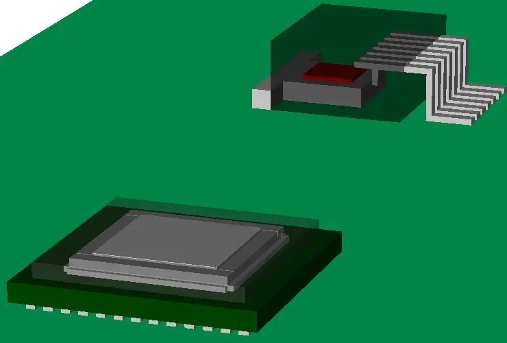 The package in the foreground is a flip chip ceramic ball grid array, commonly used for microprocessors and the like. A drop in slug is in place over the die to help spread and induce the heat to the top of the package (more on that later). The package in the background is a 7 lead TO263. A much simpler package design commonly employed for discrete power devices. In both cases the encapsulant is made a little transparent so you can see what’s inside.
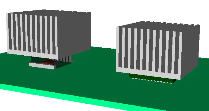 In FloTHERM they were placed on a 2S2P high-k type test board and put into a moving air stream, T=35degC, speed=3m/s (~600 lfm). Their junction temperatures (Tj) noted, that is the temperature at the heat source, in the silicon die itself. A couple of pretty standard aluminium extruded plate fin heatsinks were then placed on the top of each package and Tjs noted again.
When comparing and contrasting the thermal performance of two or more electronic products or configurations it’s best to look at ratios of temperature rises above ambient temperature. If you ever see a ratio of absolute junction temperatures quoted stick up your hand like you used to do at school and complain. The %errors/differences you get that way are much lower than they should be.
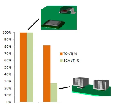 In this case the junction temperature rise above ambient when a heatsink was used on the BGA package was 27% of the value without one, a massive drop. For the TO package it had dropped to 81% of the temperature rise without a heatsink.
I’ll come clean here and admit to my surprise that there was as much temperature drop for the TO package as was seen. We’ll get onto internal package construction and how that is the thing that drives the decision what type of heatsinking (and where) to use in a later blog. I’ll also show how an understanding of the full air flow behaviour can provide reasons to unexpected thermal performance.
Suffice to say that not all package styles are equal and for heatsinks to work effectively they have to be placed where there is heat to sink (rather area extend). For now I’ll leave you with an animation of the air flow and get on to the second part of this series…
 13th March 2013, Ross-on-Wye

