Introduction
In recent years, the power density of server racks has surged past 100 kW/rack [1] to support compute-intensive workloads such as artificial intelligence and data analytics. Cooling systems play an increasingly important role in enabling such densification improvements and in improving overall data center energy consumption, equipment reliability, and total cost of ownership (TCO). One common metric for cooling system efficiency is power usage effectiveness (PUE), defined as:

PUE is always greater than 1 and the closer PUE is to 1, the more energy efficient the data center. The dominant source of non-IT equipment power is typically cooling equipment. Traditional aircooling methods are inefficient for ultra-dense server racks due to high airflow requirements, and for very high-power racks, air-cooling is simply not an option. As a result, liquid-cooling solutions are increasingly being adopted. Compared to air, liquidcooling systems can provide lower system thermal resistance, with benefits like better efficiency, lower noise and improved thermal performance [2]. These systems may employ direct-to-chip or immersion cooling and can have either single-phase (liquid-only) fluids or two-phase (liquid-vapor) fluids, which utilize the latent heat of vaporization. Single-phase cooling offers simpler flow management than two-phase cooling, while two-phase cooling provides higher heat transfer capabilities at lower power and more uniform chip temperatures, making it particularly attractive for next-generation, high-density data centers.
Heat absorbed from the rack must ultimately be rejected to the ambient air outside the data center, typically using outdoor condensers consisting of microchannel or tube-fin coil heat exchangers. Key performance metrics for a condenser array are heat rejection, power consumption, and size. Often, these metrics are combined into terms such as condenser efficiency PUEcondenser and heat rejection density (kW/m2 or kW/ft2). PUEcondenser is defined as:

This article provides guidelines to condenser designers of liquid cooled systems (both pumped 2-phase and direct expansion systems) for estimating and maximizing two-phase refrigerant-to-air condenser array performance for a given application.
What are the key design parameters for a condenser array?
1. Fan Selection
Condenser fans should be selected to provide adequate mass flow ṁair,req,total at given ambient conditions with minimum power while meeting targets for cost, size, reliability, and noise level.

Here, Q̇ is the total heat rejection capacity, cp is the air specific heat capacity and ΔT is average air temperature rise.
When aiming for lowest PUEcondenser, many large fans operating at low RPM is usually preferred, as energy efficiency rises with lower air velocity because power is proportional to the cube of velocity. This approach also tends to reduce noise and improve reliability, as there are redundant fans in the array in case of fan failure(s). The primary downsides of increasing fan count are system size and capital cost/TCO, so these must also be kept reasonable. Condenser array design should be aimed towards best energy efficiency (lowest electrical input to fan and pump) while still ensuring reasonable heat rejection per area footprint and capital cost/ TCO.
2. Condenser Geometry Selection
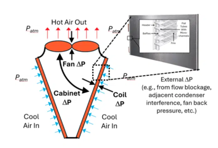
A typical commercially available condenser might consist of 2 microchannel coils placed at an angle to form a V (referred to in this article as an “MCV”) as shown in Figure 1. A microchannel coil consists of multiple flattened tubes containing microchannels and fins enclosed within inlet and outlet headers. Refrigerant circulates within the headers and microchannels, conducting heat to the fins where it can be removed by cross-directional airflow.
microchannel coil adapted from [5] and [6].
The air-side operating point of a condenser is governed by the following equations.


where Coil Air ΔP is the pressure drop across the two coil faces, Cabinet Air ΔP is the pressure drop for the air to flow from the internal coil face to the fan, and External Air ΔP is the pressure drop due to flow blockage outside the condenser, e.g. due to adjacent condenser interference. A low total system Air ΔP is desirable, as it leads to higher fan flow rate and higher heat rejection at a given fan RPM. Furthermore, the width, height and angle of the coils can be optimized to balance footprint, coil area/fan area ratio, interference between coils, and pressure drop inside the condenser.
Aside from the geometrical arrangement of the coils, parameters such as flat tube thickness, height, and spacing, microchannel size and quantity, fin pitch and shape need to be optimized. Typically, changes in refrigerant flow area will affect the balance between pumping power and refrigerant side heat transfer while an increase in fin density/blockage will affect the tradeoff between air-side heat transfer and fan power.
3. Array configuration
Condenser arrays typically comprise multiple rows of condensers connected in parallel with common vapor and liquid line headers. Figure 2 shows an example condenser array arrangement for a modular data center. An important factor in condenser array design is maintaining optimal spacing between individual units. If spacing is too tight, inner coils may be starved due to insufficient airflow. Increasing spacing between individual condensers in an array helps balance airflow across all coils, improving performance, but reducing heat rejection density.

Enjoying this article?
Subscribe to Electronics Cooling for practical, engineer-focused insight on today’s thermal management challenges—plus immediate access to new digital magazine issues.
Subscribe here →
Step-by-step design optimization methodology
This section illustrates how to optimize PUEcondenser of a MCV condenser array with a certain footprint area and capable of rejecting a given heat load. The general steps for this analysis are:
Step 1: Determine the total required airflow, ṁair,req,total for the condenser array using Eq. (3).
Step 2: Make an initial guess for the condenser array configuration, such as 2 rows that each contain 5 condensers. Use this guess to estimate the number of fans in the array and calculate the airflow each fan needs to provide.
Step 3: Select a fan that is compact enough to fit all condensers in the given footprint area and that can provide the airflow calculated in Step 1 with no more than the maximum allowed power. Consider reasonable margins for both.
Step 4: Calculate the refrigerant mass flow rate through each coil using
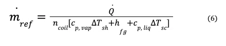
ṁref is the total refrigerant mass flow rate
ncoil is the total number of coils
And at design temperature and pressure,
cp,vap is the refrigerant vapor specific heat
ΔTsh is the vapor superheat entering the condenser
hfg is the refrigerant latent heat
cp,liq is the refrigerant liquid specific heat
ΔTsc is the desired refrigerant sub-cool exiting the condenser
Step 5: For the calculated ṁref, use a commercially available microchannel coil design software such as CoilDesigner [3] or heat transfer correlations (air-side heat transfer correlation [4], two-phase refrigerant heat transfer correlation [5] and single-phase refrigerant heat transfer correlation [6] ) to determine the minimum per coil air mass flow rate ṁair,req to maintain the desired subcool at the condenser exit.
Step 6: Run CFD simulations of the initial array to determine the average air velocity across each coil at various fan RPMs and select the lowest RPM that can deliver at least ṁair,req (calculated in Step 5) in every coil.
Step 7: Calculate the total input fan power Pfan for the condenser array using fan power curves from the fan data sheet.
Step 8: Calculate total input pump power Ppump for refrigerant flow by summing up contributions from all coils using:
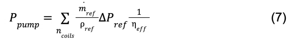
where Pref is the average refrigerant density in the coil, ΔPref is the refrigerant pressure drop across each coil calculated using two-phase microchannel correlations [7], and ηeff is the net pump efficiency.
Step 9: Sum the array fan and pump power to determine total cooling power requirements of the array. Use the coil design software or heat transfer correlations referenced above to determine the total heat rejection in all coils and use eq. (2) to calculate PUEcondenser.
Step 10: Use component cost models to obtain TCO of the condenser array over a 10-year period (Initial capital cost + 10 x Annual operating and maintenance cost).
Step 11: Prepare a plot of PUEcondenser vs TCO for different condenser arrays to select the optimum combination.
isolated MCV condenser.
Sample Calculations
Consider an MCV condenser array design for a 1 MW modular data center with footprint area 12.2m x 2.4m (40’x8’) and ambient air temperature of 40°C. Refrigerant entering every 1.02mx1.52m (40”x60”) rectangular coil in the array is assumed to be saturated vapor at 60°C. The purpose of the study is to understand the tradeoff between PUEcondenser and TCO of a condenser array with multiple uniformly spaced condensers. A bounding condition for fan RPM is that the exit degree of subcooling for every condenser in the array is at least 3°C.
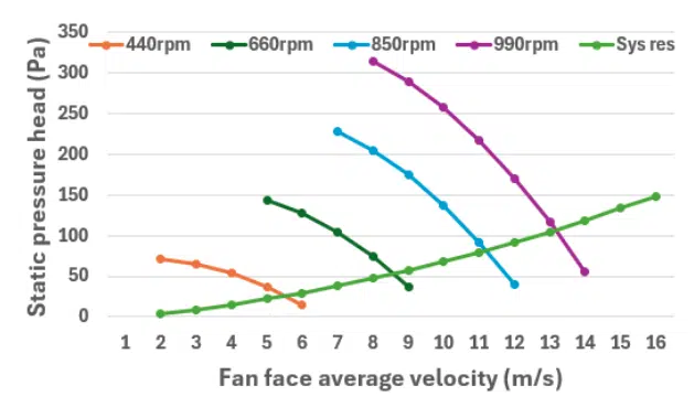
The required total air flow rate through the condenser array is determined to be 200,000 m3/hr (117716 cfm) using Eq. (3) considering Q̇ = 1000 kW, cp = 1.004 kJ/(kg.K) and ΔT = 16°C corresponding to an approach temperature (difference between refrigerant saturation temperature and air outlet temperature) of 4°C for the ambient air. A commercially available fan was selected to accommodate an initial configuration of 10 condensers (2 rows, 5 columns); this fan was chosen to be as large as possible to fill the allowable space and has fan curves exhibited in Figure 3. CFD models were built, and steps 1-10 were followed for the initial configuration. The process was repeated for 12, 14, 16, 18 and 20 condensers, all with 2 rows.
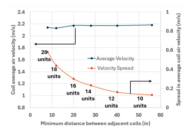
Average coil velocity was computed for every coil in the array to determine: (1) Mean of area-averaged coil velocity in all coils in the array and (2) Velocity spread defined by difference between largest average coil velocity and lowest average coil velocity. Figure 4 shows sample results for 660 RPM fan speed. The mean coil velocity hardly changes with condenser spacing while velocity spread decreases with condenser spacing. A high velocity spread indicates strong interference effects due to the outer coils in the air receiving larger airflow compared to the inner coils. Figure 4 shows that velocity spread begins leveling off as condenser spacing increases past 0.51m (20 inches). The exact spacing chosen will depend on a particular application’s desired balance between compactness and efficiency.
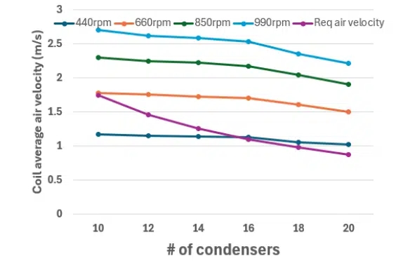
Figure 5 compares individual coil “required” average air velocity calculated using CoilDesigner software by following Step 5 (to maintain at least 3°C subcool at coil exit), with the lowest coil air velocity in the innermost coil of the stack, that can be provided by fans operating at 4 different RPMs.
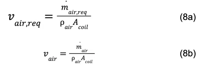
where ρair is the air density at ambient temperature and pressure, and Acoil is the coil face area. With more condensers, vair,req decreases because a lower refrigerant flow rate ṁref needs to be condensed in every coil. The fan RPM required to obtain the minimum required vair,req is obtained by interpolating between vair delivered by the different fan RPMs.
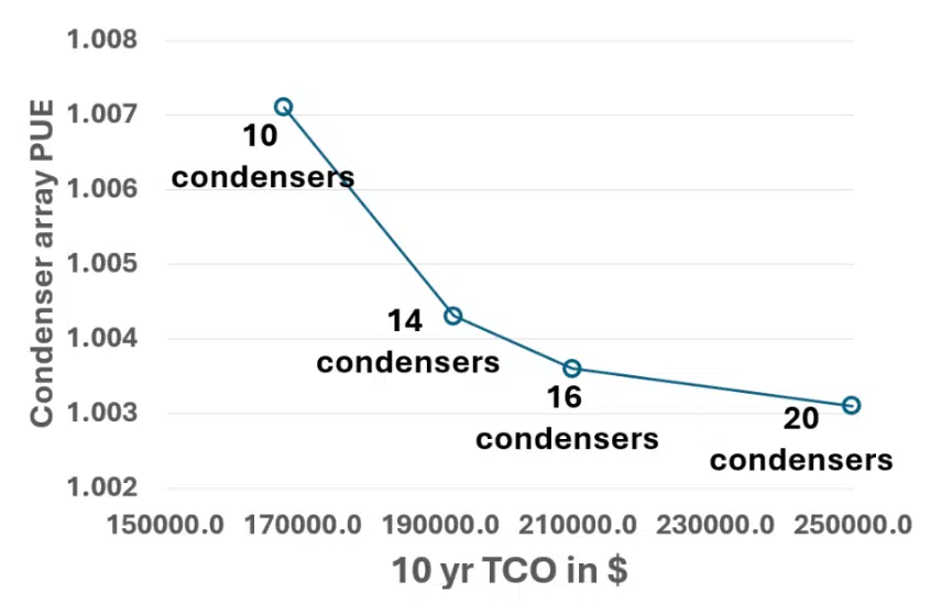
Table 1 summarizes minimum vair,req in every coil, input fan power and pump power for the different arrays. Total pump power is significantly lower than the total fan power for every array, and the lowest input power is obtained for the 20-condenser array. However, the TCO of the 20-condenser array can be prohibitive. The plot shown in Figure 6 demonstrates that PUEcondenser changes marginally going from 16 to 20 condenser array and hence 16 condenser array exhibits a good balance between PUEcondenser and TCO.
| No. of Condensers | vair,req (m/s) |
Fan RPM | Individual Fan Power (kW) |
Total Fan Power (kW) |
Pump Power for Single Coil (kW) |
Total Pump Power (kW) |
Total Input Power (kW) |
|---|---|---|---|---|---|---|---|
| 10 | 1.75 | 633 | 0.66 | 6.6 | 0.022 | 0.44 | 7.1 |
| 14 | 1.25 | 455 | 0.29 | 4.0 | 0.016 | 0.29 | 4.3 |
| 16 | 1.09 | 394 | 0.21 | 3.3 | 0.014 | 0.24 | 3.6 |
| 20 | 0.87 | 324 | 0.15 | 3.0 | 0.011 | 0.19 | 3.1 |
Table 1: Summary of input fan power and pump power for different condenser arrays.
condensers.
Conclusions
This article presented a structured design methodology for microchannel condensers used in two-phase liquid-cooled data centers. It provided guidelines on selecting fan size and quantity, fan RPM, coil geometry, and spacing between adjacent condensers to attain the best balance between efficiency and cost.
Acknowledgements
Financial support for this work is provided by the US Department of Energy through the ARPA-E COOLERCHIPS project (Award no. DE-AR00001763). The authors would like to thank Timothy Schrader and Russ Tipton, researchers at Vertiv, for their discussions and assistance with documentation of the approach for optimizing condenser array design.
References
[1] “https://www.ramboll.com,” March 2024. [Online]. Available: https://www.ramboll.com/en-us/insights/decarbonise-for-netzero/ 100-kw-per-rack-data-centers-evolution-power-density.
[2] A. Capozzoli and G. Primiceri, “Cooling systems in data centers: state of art and emerging technologies,” in Energy Procedia, 2015.
[3] “CoilDesigner,” [Online]. Available: https://optimizedthermalsystems.com/coildesigner/.
[4] K. Man-Hoe and C. W. Bullard, “Air-side thermal hydraulic performance of multi-louvered fin aluminum heat exchangers,” International Journal of Refrigerant, no. 25, pp. 390-400, 2002.
[5] E. Jassim, T. Newell and J. Chato, “Modeling of Two-Phase Heat Transfer in Smooth Tubes Using Probabilistic Flow Regime Maps,” in The International Refrigeration and Air Conditioning Conference, 2006.
[6] D. Taler and J. Taler, “Simple heat transfer correlations for turbulent tube flow,” in E3S Web of Conferences, 2017.
[7] M. Shah, “New general correlation for heat transfer during saturated boiling in mini and macrro channels,” International Journal of Refrigeration, vol. 137, pp. 103-116, 2022.