
In April 2025, Google announced its 1 MW 42U rack [1], marking a turning point in data center thermal management where traditional air cooling can no longer support the extreme power densities of modern hardware. As chip thermal design power (TDP) continues to grow, data centers must replace air-cooled heat sinks with liquid-cooled cold plates [2]. Cold plates transfer heat from a heat-generating component into a pumped liquid coolant, typically utilizing enhancements such as pins or fins to increase convective heat transfer area. To maintain safe operating temperatures with rising TDP, the heat removal capabilities of the cold plate can be increased by increasing the coolant flow rate, decreasing the coolant inlet temperature, or improving the cold plate performance. Each of these options comes with a tradeoff. Increasing flow rate increases pumping power; lowering coolant temperature increases the load on facility chillers and increases energy consumption; and improvements in cold plate performance require innovative cold plate designs that may be more difficult or costly to manufacture. As the data center industry drives toward more efficient cooling systems, high performance cold plates, characterized by low thermal resistance and pressure drop, are increasingly important.
In a liquid-cooled computer having a conventional lidded package, the silicon chip is bonded to a protective metal lid called the integrated heat spreader (IHS), using a layer of thermal interface material (TIM). The cold plate is mounted to the IHS with a second layer of TIM. The chip-to-coolant thermal pathway is chip → TIM1 → IHS → TIM2 → cold plate, with each component adding a thermal resistance to heat flow. The total thermal resistance is the sum of the thermal resistances in series. To reduce thermal resistance, one design option is to employ de-lidded, direct-to-die cooling. By removing the IHS, the cold plate can be mounted directly to the silicon with a single layer of TIM. The de-lidded architecture shortens the thermal pathway compared to the conventional lidded stack and can significantly reduce the total thermal resistance.
Unfortunately, removing the IHS increases the risk of mechanical failure. The cold plate and silicon chip have different coefficients of thermal expansion (CTE), meaning they expand at different rates when heated. Common cold plate materials, such as copper (CTE = 16.6 ppm/°C) and aluminum (CTE = 22.5 ppm/°C), have significantly greater CTE values than silicon (CTE = 3 ppm/°C) [3]. During thermal cycling, where the chip heats up under load and cools down while idle, the dissimilar expansion of the cold plate and silicon chip leads to warpage. Over time, this warpage can pump the TIM from the interface, causing uneven contact, localized hot spots, and accelerated device failure. A cold plate made from a low CTE material may mitigate this challenge. However, for metals there is typically an inverse relationship between CTE and thermal conductivity. While low CTE materials may reduce warpage, poor thermal conductivity increases thermal resistance.
We recently developed [4] a cold plate made from copper tungsten (CuW, 10% Cu / 90% W by weight). CuW offers relatively high thermal conductivity (k = 174 W/(m-K)) [5] and a closer CTE match (6.5 ppm/°C) to silicon, as compared to pure Cu. We also designed a high-performance diamond-shaped pin geometry that enables low thermal resistance and low pressure drop. The goal was to reduce plate warpage that arises from CTE mismatch while maintaining high thermal and hydraulic performance. The remainder of this article describes design and testing of the cold plate.
Cold Plate Design
Figure 1 shows the cold plate design, which is intended to cool a 75 mm × 75 mm heat source dissipating 1000 W uniformly (heat flux of q” = 17.78 W/cm2). The base is 2 mm thick. Inlet and outlet plenums distribute flow among the pins. The pattern of staggered diamond-shaped pin fins, shown in Figure 1(C), is characterized by four geometric parameters: height H = 4 mm, spacing S = 0.5 mm, pin width X = 1 mm, and pin length Y = 4 mm.
The diamond-shaped pin cold plate shown here was found by searching a design space of more than 300 cold plate designs using finite element simulations. We systematically varied the pin geometry and identified the design with both the lowest thermal resistance (Rth=(Tmax-Tin)/Q) and pressure drop (Pin-Pout) at a flow rate of 3 liters per minute. Here thermal resistance is calculated using the maximum chip temperature (Tmax), fluid inlet temperature (Tin), and the 1000 W heat source (Q). Pressure drop is calculated using the difference in time-averaged pressure between the fluid inlet and outlet during steady state operation.
Fabrication and Testing
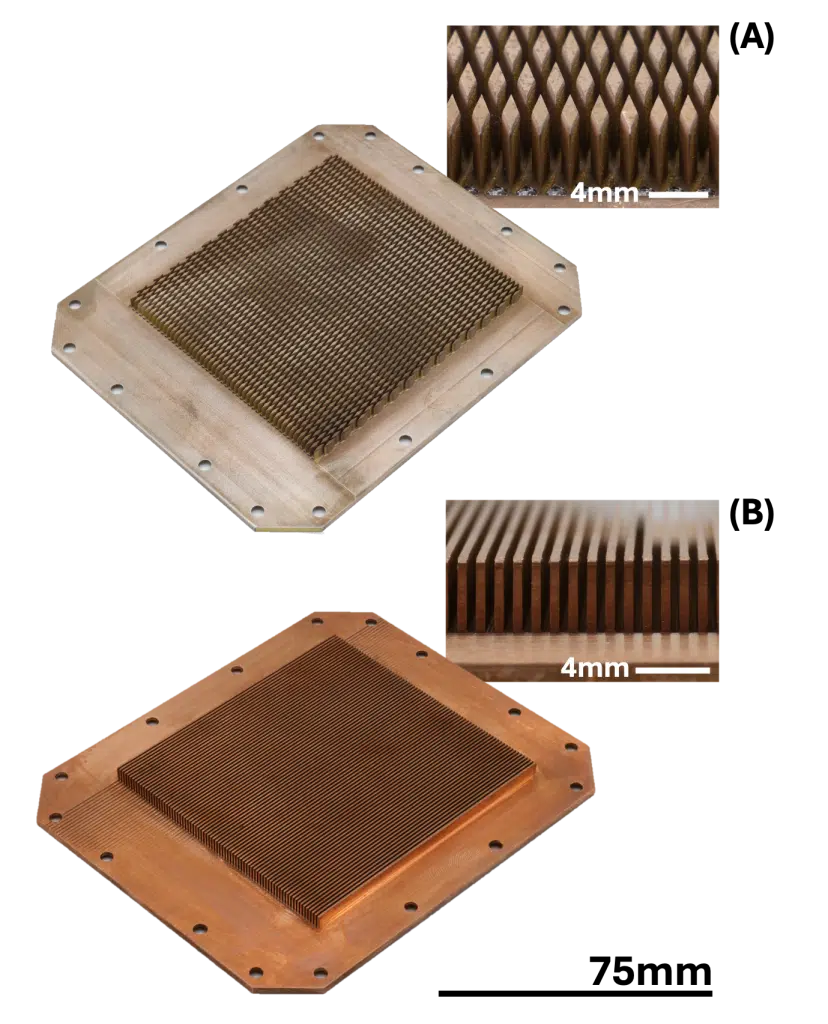
We fabricated the diamond-shaped pin cold plate in both CuW and Cu. For comparison purposes, we also designed and fabricated cold plates with straight fins, also from CuW and Cu. The straight fin design features 0.5 mm fin width, 0.5 mm channel spacing, and 4 mm fin height. Both diamond-shaped pin and straight fin geometries have a minimum feature size of 0.5 mm to ensure similar manufacturing difficulty and a fair performance comparison. The pin/fin height of 4 mm was selected to balance thermal performance and pressure drop. All plates were produced using wire electrical discharge machining (EDM). Figure 2 shows a CuW diamond-shaped pin cold plate and Cu straight fin cold plate.
The thermal-hydraulic performance of each cold plate was measured on a custom flow loop using a 75 mm × 75 mm calorimeter bar designed to emulate the footprint of future generation GPUs. A controlled 1000 W was dissipated through the top surface of the calorimeter bar via cartridge heaters. To minimize heat dissipation to the environment, five sides of the calorimeter bar were insulated with a quarter inch ceramic layer and neoprene rubber foam. Four vertically embedded resistance temperature detectors (RTDs) measured the internal temperature gradient within the calorimeter bar. Using the data from these sensors, we performed a linear extrapolation to determine the heater surface temperature. To ensure good thermal contact between the calorimeter bar and cold plate, a layer of TIM (GT90 Pro, 1.2 K/kW thermal resistance over 75 mm × 75 mm area [6]) was applied. The measured chip-to-coolant thermal resistance is defined from the calorimeter bar top surface (at the center) to the coolant inlet and includes both the contribution from the TIM and cold plate. The coolant was single phase water for all tests.
Enjoying this article?
Subscribe to Electronics Cooling for practical, engineer-focused insight on today’s thermal management challenges—plus immediate access to new digital magazine issues.
Subscribe here →
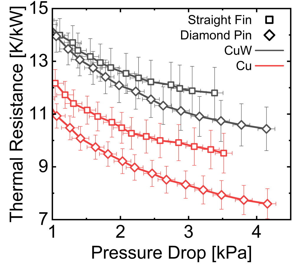
Figure 3 shows the measured chip-to-coolant thermal resistance for all four cold plates as a function of pressure drop across a flow rate range of 1.7 to 3.8 LPM. Both geometric and material trends emerge from the data. First, the diamond-shaped pin geometry achieves lower thermal resistance, but greater pressure drop, than the straight fin geometry across all tested flow rates. At 3.8 LPM the pressure drop through diamond-shaped pins is 0.65 kPa higher than through the straight fins. Second, Cu plates consistently achieve lower thermal resistance than CuW, due to the higher thermal conductivity of Cu. The lowest measured thermal resistance was 7.6 K/kW, achieved by the Cu diamond-shaped pin plate at 4.15 kPa pressure drop. The CuW diamond-shaped pin plate reached 10.4 K/kW at 4.14 kPa pressure drop.
The diamond-shaped pin geometry achieves lower thermal resistance compared to straight fins despite having 4.2% less heat transfer surface area. This reduction is driven by the fluid behavior. While the continuous channels of straight fins confine the fluid and allow the thermal boundary layer to thicken, the staggered pins constantly interrupt the flow, restarting thermal boundary layer development and enhancing mixing. As a result, diamond-shaped pins achieve 9% to 20% lower thermal resistance than straight fins beyond 2 LPM, with the relative advantage of diamond-shaped pins growing with increasing flow rate.
Predicting Warpage
The motivation for using CuW is to mitigate thermally induced warpage and ensure long term reliability of the component. We developed finite element simulations in COMSOL Multiphysics v 6.3 [7] to predict this warpage across designs and materials. Figure 4 shows the warpage prediction. First, the CFD model solves the temperature field for a flow rate of 3 LPM. The temperature field is used as an input to the structural simulation. Because cold plates are mounted, not bonded, to the IT component, warpage of the cold plate is driven by thermal expansion reacting against rigid mounting hardware rather than load from the expanding chip. As such, the model excludes the silicon chip and TIM. To emulate realistic constraints from the cold plate mounting, fixed boundary conditions were applied to the outer perimeter of the cold plate base. The resulting warpage profile corresponds to the diagonal length of the 75 mm × 75 mm heated surface. Depending on temperature, material, and geometry, the magnitude of warpage is in the order of tens to hundreds of microns.
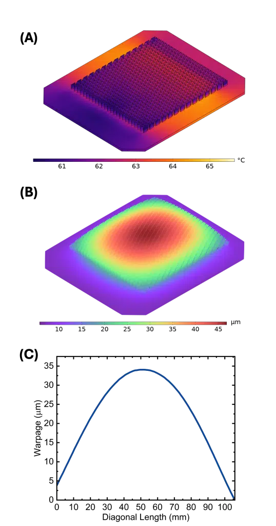
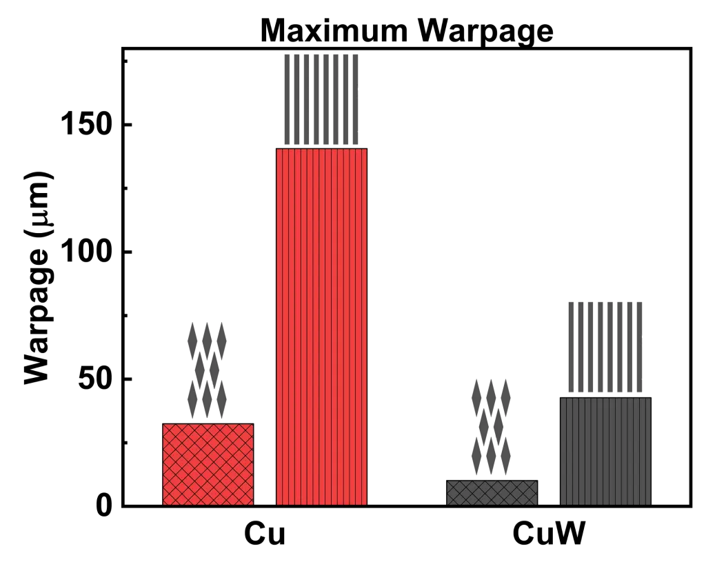
Figure 5 shows the maximum predicted warpage for diamond-shaped pins and straight fins across Cu and CuW. As with the thermal-hydraulic performance, there are both geometric and material trends. Straight fins exhibit roughly 4.2 times greater warpage than diamond-shaped pins for a given material. The discontinuous arrangement of diamond-shaped pins relieves stress build up, ultimately resulting in a lower bending moment compared to the continuous straight fin geometry. Similarly, Cu exhibits roughly 3.2 times greater warpage than CuW given the same geometry. This is primarily due to the CTE of Cu being 2.6 times greater than CuW. A secondary impact is the lower thermal conductivity of CuW compared to Cu results in a steeper temperature gradient across the cold plate base. Differential expansion between the hotter bottom surface and cooler top surface of the cold plate base induces a concave-up curvature, which opposes the global concave-down curvature and reduces the total warpage beyond the CTE ratio.
Conclusion
This article describes the thermal-hydraulic and mechanical benefits of CuW cold plates featuring diamond-shaped pins. Our results demonstrate that diamond-shaped pins provide superior thermal-hydraulic performance compared to conventional straight fins. Importantly, this comparison uses a single diamond-shaped pin geometry selected for a specific pressure drop range. The ideal design is dictated by the pressure drop budget of the cooling system. A higher pressure drop budget would allow for an even more aggressive design, further widening the performance gap between diamond-shaped pins and straight fins. CuW proves to be a promising cold plate material, capable of achieving low thermal resistance while offering a much closer CTE match to silicon and significantly less warpage than Cu.
CuW has higher hardness than Cu, which presents advantages and disadvantages. While the higher hardness of CuW makes it more difficult to machine than Cu, the diamond-shaped pin geometry allows for straight machining passes compatible with CNC machining or wire EDM. The high hardness may also prove advantageous in emerging 1 MW rack architectures, which require high coolant flow rates. CuW offers superior resistance to erosion-corrosion compared to Cu, potentially extending component lifespan under high coolant velocity. Alternate compositions of CuW, or other CTE matched materials, may be considered to balance the thermal performance, reliability, and cost. For example, a higher copper content CuW would decrease thermal resistance and cost at the expense of higher CTE.
As the computer industry faces growing challenges from increasing die size, TDP, and coolant flow rates, the thermal burden on cold plates to maintain safe chip temperatures will increase. Large-die packages will be especially susceptible to warpage-induced failure, suggesting that cold plate reliability may need to play a larger role in the design process compared to purely thermal performance. Geometric enhancements, such as diamond-shaped pins, or low CTE materials, such as CuW, may prove beneficial to address the evolving challenges and serve as valuable enablers of next generation data center cooling.
References
[1] M. Iyngar, A. Huffman, AI infrastructure is hot. New power distribution and liquid cooling infrastructure can help, Https://Cloud. Google.Com/Blog/Topics/Systems/Enabling-1-Mw-It-Racks-and-Liquid-Cooling-at-Ocp-Emea-Summit (2025).
[2] R. Kong, H. Zhang, M. Tang, H. Zou, C. Tian, T. Ding, Enhancing data center cooling efficiency and ability: A comprehensive review of direct liquid cooling technologies, Energy 308 (2024). https://doi.org/10.1016/j.energy.2024.132846.
[3] G K White, Thermal expansion of reference materials: copper, silica and silicon, J Phys D Appl Phys 6 (1973) 2070–2078.
[4] I. Pinkus, W.Y. Park, V. Ganesan, O.M. Zaki, T.G. Aguirre, K. Nawaz, N. Miljkovic, W.P. King, Ultra-low thermal resistance and pressure drop copper and copper-tungsten diamond-shaped pin fin cold plates for liquid cooling of electronics, Int J Heat Mass Transfer 256 (2026). https://doi.org/10.1016/j.ijheatmasstransfer.2025.128080.
[5] S.H. Lee, S.Y. Kwon, H.J. Ham, Thermal conductivity of tungsten-copper composites, in: Thermochim Acta, 2012: pp. 2–5. https:// doi.org/10.1016/j.tca.2012.03.022.
[6] Smart High Tech, GT90PRO Datasheet, n.d. https://smarthightech.com/product/gt90pro/ (accessed December 21, 2025).
[7] COMSOL Multiphysics® v. 6.3. www.comsol.com. COMSOL AB, Stockholm, Sweden

