
ABSTRACT
Power densities continue to increase in AI servers, high-performance computing (HPC) systems, electric vehicles, and semiconductor manufacturing equipment.
As a result, thermal management has become a critical system-design requirement.
Thermal solutions often fall short not because one material lacks performance, but because the complete thermal path has not been engineered as a system.
This application note explains how heat travels through high-power electronic systems, why thermal performance must be evaluated across the full heat-transfer path, and how materials such as thermal interface materials, vapor chambers, indium foil, and liquid metal can be integrated to reduce thermal resistance and support long-term reliability.
INTRODUCTION
Thermal management is often approached as a material-selection problem.
Designers may focus on choosing a high-conductivity thermal interface material (TIM) or a larger heatsink, expecting improved performance.
However, in high-power systems, cooling efficiency depends on the entire path through which heat travels.
A well-designed thermal solution must consider:
- Heat flux density
- Interfacial thermal resistance
- Interface thickness and conformity
- Contact pressure
- Heat spreading capability
- Heat rejection capacity
- Long-term material stability
- Manufacturing consistency
As system power continues to rise, thermal design must shift from selecting individual materials to optimizing the complete thermal path.
The best result usually comes from matching the interface material, heat spreader, mechanical stack-up, and cooling method to the actual operating conditions of the assembly.
UNDERSTANDING THE THERMAL PATH
A thermal path is the complete route through which heat moves from the source to the external environment.
A typical thermal path concept is depicted in the graphic below:
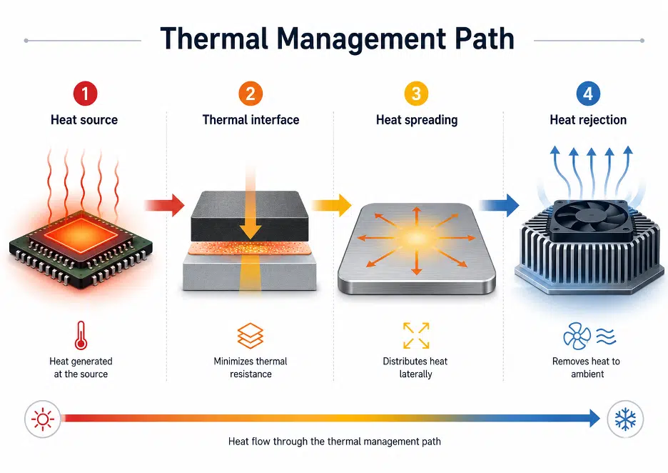
Each section contributes to the total thermal resistance of the system.
Even if one component has excellent thermal conductivity, poor performance in another section can limit the overall cooling result.
The key principle is:
Cooling performance is only as strong as the weakest point in the thermal path.
For example, a high-performance heatsink cannot compensate for a poorly applied thermal interface material.
Similarly, a low-resistance interface will not deliver the expected benefit if heat spreading or airflow is insufficient.
In practical design work, the full thermal path should be reviewed as a resistance chain. A simplified model can be considered as:
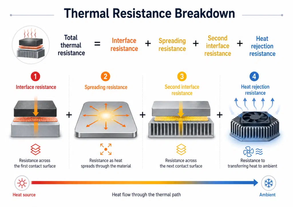
This does not replace detailed simulation or physical testing, but it helps identify where the largest thermal penalty is likely to occur.
In many designs, the limiting factor is not the datasheet conductivity of a single material. It is the combined effect of bondline thickness, pressure, surface flatness, spreading area, airflow, coolant temperature, and assembly variation.
Enjoying this article?
Subscribe to Electronics Cooling for practical, engineer-focused insight on today’s thermal management challenges—plus immediate access to new digital magazine issues.
Subscribe here →
KEY THERMAL DESIGN CHALLENGES
Excessive Interfacial Thermal Resistance
The interface between two solid surfaces is often one of the most critical thermal bottlenecks. Even surfaces that appear smooth contain microscopic roughness.
Contact occurs at surface asperities, while small voids between the surfaces trap air. Because air is a poor thermal conductor, these voids increase contact resistance and reduce heat-transfer efficiency.
Common causes of interfacial thermal resistance include:
- Excessive TIM thickness
- Uneven material application
- Surface roughness
- Insufficient contact pressure
- Poor interface conformity
- Assembly tolerances that create variable gaps
Mitigating this issue requires proper material selection, controlled bondline thickness, clean contact surfaces, and uniform pressure.
In production, the selected material must also tolerate real assembly variation without creating inconsistent thermal performance from unit to unit.
Ineffective Heat Spreading
High-power components often generate localized hotspots. If heat is not spread efficiently, temperature concentration can occur near the source, causing reduced performance, throttling, or reliability issues.
Heat spreading is especially important in:
- AI accelerators
- CPUs and GPUs
- Power modules
- Laser systems
- Semiconductor process equipment
- Compact electronic assemblies with limited heatsink area
Vapor chambers, heat pipes, graphite sheets, and metal heat spreaders are commonly used to distribute localized heat over a larger area before it reaches the heatsink, cold plate, chassis, or other heat rejection structure.
The goal is not only to move heat away from the source, but to lower peak temperature and improve temperature uniformity across the cooling surface.
Insufficient Heat Rejection
After heat is transferred and spread, it must be removed from the system. If the heatsink, airflow, liquid cooling loop, cold plate, or enclosure path is undersized, the system will still overheat.
Common issues include:
- Undersized heatsinks
- Poor airflow design
- Inadequate liquid cooling capacity
- Thermal bottlenecks at the hot side of the cooling structure
- Mismatch between actual and assumed heat load
- Ambient or coolant temperature assumptions that do not reflect worst-case operation
Heat rejection components should be designed based on real operating conditions, not only nominal power values.
Designers should also account for airflow restrictions, dust loading, altitude, fan curves, coolant temperature rise, duty cycle, and nearby heat sources when applicable.
Long-Term Reliability Degradation
Thermal materials must maintain performance over time. Polymer-based TIMs may experience pump-out, dry-out, cracking, compression set, or aging under thermal cycling. These changes can increase thermal resistance and reduce cooling performance.
Reliability concerns are especially important in:
- Automotive electronics
- Aerospace and defense systems
- Semiconductor equipment
- Data centers
- High-duty-cycle industrial systems
- Field-deployed electronics exposed to vibration or wide temperature swings
Material stability should be evaluated under the expected temperature, pressure, vibration, and environmental conditions.
Validation may include thermal cycling, power cycling, high-temperature aging, vibration or shock testing, and post-test thermal impedance measurement.
Visual inspection can also help identify voiding, migration, cracking, pump-out, or other material changes that may affect long-term performance.

MATERIAL ROLES WITHIN THE THERMAL PATH
Different thermal materials perform different functions. Effective thermal design requires selecting materials based on their role in the system, rather than assessing thermal conductivity values alone.
The right solution depends on the interface geometry, pressure, reliability requirements, electrical requirements, and manufacturing process.
Vapor Chamber
A vapor chamber is used to spread heat rapidly from localized hotspots.
It is not a replacement for interface design, but a heat-spreading component that can reduce peak temperature before heat is transferred into the next part of the cooling structure.
Primary functions:
- Distributes heat over a larger surface area
- Reduces hotspot temperature
- Improves temperature uniformity
- Supports compact, high-power designs
- Helps reduce the heat flux presented to a heatsink or cold plate
Vapor chambers are well suited for high heat flux applications where conventional solid heat spreaders may not provide sufficient thermal spreading.
They should be integrated early in the mechanical design process, since package size, mounting method, orientation, contact area, and interface pressure can all affect performance.
Thermal Interface Materials
Thermal interface materials are used to fill microscopic gaps between mating surfaces and reduce interfacial thermal resistance.
Common TIM functions:
- Improve contact between surfaces
- Replace air gaps with thermally conductive material
- Compensate for surface roughness
- Accommodate mechanical tolerances
- Support repeatable assembly processes
TIM performance depends heavily on:
- Bondline thickness
- Contact pressure
- Surface condition
- Material conformity
- Thermal impedance at the actual installed thickness
- Long-term stability
A high-conductivity TIM can still perform poorly if applied too thickly, installed under insufficient pressure, or used across a gap it was not intended to fill.
For this reason, engineers should evaluate thermal impedance under representative assembly conditions rather than relying only on bulk thermal conductivity.
Thermal Pads, Putties, Pastes and Phase Change Materials
TIMs are not interchangeable. Each format has strengths and limitations.
Thermal pads are useful where a defined thickness, electrical insulation, clean handling, or die-cut geometry is required. They can also help accommodate tolerance stack-ups, although excessive compression or inadequate pressure can affect performance.
Thermal putties and gap fillers are useful when component heights vary, surfaces are uneven, or a dispensable material is preferred for automated assembly. They can conform well to complex geometries, but dispensing control, placement, rework, and contamination risk should be considered.
Thermal pastes and greases can provide low bondline thickness and good wetting between smooth surfaces, but they require controlled application. Over-application, voiding, pump-out, and process variation can reduce consistency in production.
Phase change materials are applied as solids or films and soften at elevated temperature to improve wetting at the interface. They can be useful when cleaner handling is needed than grease, while still improving surface contact during operation.
Indium Foil
Indium foil is a metal-based thermal interface material known for high thermal conductivity, excellent ductility, and stable long-term behavior.
Advantages of indium foil:
- High thermal conductivity
- Excellent surface conformity
- Stable performance under low pressure
- No pump-out or dry-out
- Good reworkability
- Suitability for vacuum and high-reliability environments

Indium foil is commonly used when reliability, stability, and controlled interface performance are more important than low-cost mass application.
It can be especially useful where polymer-based materials may not provide the desired long-term stability.
Design teams should still evaluate surface finish, oxidation, pressure, handling, and material compatibility for the specific assembly.
Liquid Metal
Liquid metal can provide extremely low interfacial thermal resistance and an ultra-thin bondline in carefully controlled assemblies.
Key characteristics:
- Very low thermal resistance
- Ultra-thin bondline capability
- Excellent wetting on compatible surfaces
- Strong performance potential in very high heat flux applications
However, liquid metal requires careful process control. Surface compatibility, containment, corrosion risk, electrical conductivity, and manufacturability must be considered during design.
In many cases, the thermal benefit must be weighed against the increased need for sealing, process discipline, electrical isolation strategy, and long-term compatibility testing.
Liquid metal should not be treated as a drop-in replacement for conventional TIMs. It is best suited for designs where the mechanical stack-up, containment approach, and production process can be controlled tightly enough to manage the associated risks.
PRACTICAL DESIGN GUIDELINES
Interface Design
To improve interface performance:
- Minimize TIM thickness where possible
- Use the thinnest material that still fills the gap and meets tolerance requirements
- Ensure clean and smooth contact surfaces
- Apply sufficient and uniform pressure
- Avoid air gaps and uneven material distribution
- Control assembly tolerances
- Validate the interface at the expected installed thickness and pressure
The interface should be designed as a controlled thermal joint, rather than a secondary assembly detail.
Small changes in gap, pressure, or surface condition can have a significant effect on performance.

Material Selection
Material selection should be based on operating conditions and system requirements.

The best material is not always the one with the highest thermal conductivity. It is the one that fits the full thermal path, mechanical design, manufacturing process, and application environment.
Heat Spreading
To improve heat spreading:
- Use vapor chambers or other heat spreaders in high heat flux regions
- Increase effective heat transfer area before heat reaches the heatsink or cold plate
- Avoid localized thermal concentration
- Match spreader size and thickness to heat source geometry
- Consider mechanical integration early in the design phase
- Evaluate both peak temperature and temperature uniformity
Good heat spreading reduces peak temperature and improves thermal stability across the system.
It can also improve downstream heat rejection by presenting a more uniform heat load to the cooling structure.
Heat Rejection
To improve heat rejection:
- Design heatsinks based on actual heat load
- Validate airflow or liquid cooling capacity
- Reduce thermal bottlenecks between the spreader and cooling structure
- Consider system-level airflow restrictions
- Account for environmental temperature and operating duty cycle
- Include design margin for real-world operating conditions
Heat rejection must be designed with sufficient margin for worst-case operation. If the heat rejection stage is undersized, improvements at the interface or spreading layer may not produce the expected system-level result.
System Integration
Thermal performance must be repeatable in production. A design that performs well in a prototype may fail in volume production if assembly variation is not controlled.
Important integration factors include:
- Process consistency
- Material handling
- Surface preparation
- Dispensing or placement control
- Pressure control
- Rework requirements
- Quality inspection
- Long-term reliability validation
Manufacturability should be considered from the beginning of the thermal design process.
This includes how the material will be stored, dispensed, applied, compressed, inspected, and reworked.
THERMAL PATH DESIGN CHECKLIST
Before finalizing the thermal design, engineers should confirm the following:
☐ Has the total heat load been defined under worst-case operating conditions?
☐ Has peak heat flux been reviewed, not only total power?
☐ Have all interfaces in the thermal path been identified?
☐ Has each interface been evaluated for bondline thickness, pressure, and surface condition?
☐ Is the selected TIM appropriate for the actual gap and tolerance range?
☐ Is heat spreading sufficient to reduce localized hotspots?
☐ Is the heat rejection method sized for real airflow, coolant, or ambient conditions?
☐ Has the material been evaluated for thermal cycling, aging, vibration, or other reliability requirements?
☐ Can the assembly process be repeated consistently in production?
☐ Has thermal performance been validated after environmental or reliability testing?
FROM MATERIAL SELECTION TO SYSTEM OPTIMIZATION
Modern thermal design requires a shift in thinking. Instead of asking:
“Which material has the highest thermal conductivity?”
Designers should ask:
“Where is the dominant resistance in the thermal path, and which material or structure will reduce it most effectively?”
This approach considers how materials, interfaces, mechanical structures, manufacturing processes, and cooling architecture interact.
A system-level thermal strategy can reduce total thermal resistance, improve reliability, and support scalable production.
HOW T-GLOBAL AIDS THERMAL PATH DESIGN
T-Global provides thermal materials and heat-spreading technologies that support multiple points in the thermal path.
Instead of treating TIM selection, heat spreading, and heat rejection as separate decisions, design teams can evaluate these elements together based on the requirements of the application.
![]()
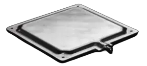
For assemblies with tolerance variation or multiple component heights:
Thermal pads, putties, and gap fillers can help improve contact and reduce air gaps.
![]()
For thin, controlled interfaces:
Pastes, phase change materials, indium foil, or liquid metal may be considered depending on pressure, reliability, and process requirements.
![]()
For localized hotspots or compact high-power designs:
Vapor chambers, heat pipes, graphite sheets, or heat spreaders can help distribute heat before it reaches the final cooling structure.
This system-level view is especially important in high-power electronics, where a single material change may not be enough to solve the thermal problem.
By matching the material format and heat-spreading method to the full operating environment, engineers can improve performance while maintaining manufacturability and long-term reliability.
DESIGNING FOR THE THERMAL PATH
As power density increases across AI servers, HPC systems, electric vehicles, and semiconductor equipment, thermal design can no longer depend on material specifications alone.
Effective thermal management requires:
- A well-designed thermal path
- Low-resistance interface engineering
- Proper heat spreading
- Sufficient heat rejection
- Application-specific material selection
- Reliable manufacturing and integration
By treating thermal management as a system-level design challenge, engineers can achieve more stable, efficient, and reliable cooling performance in high-power electronic systems.
RELATED T-GLOBAL RESOURCES
For additional material selection and design support, review these T-Global resources:
- T-Global Product Categories — Descriptions of the major elements of thermal path design
- Vapor Chamber Guide — Review vapor chamber design considerations and application examples.
- Thermal Interface Materials — Learn how TIMs reduce contact resistance between mating surfaces
- Thermal Simulation Support — Work with T-Global engineers to evaluate heat dissipation options using project requirements and CAD files.
Need help evaluating the full thermal path? Contact T-Global to discuss material selection, heat spreading, and simulation support for your application.

